
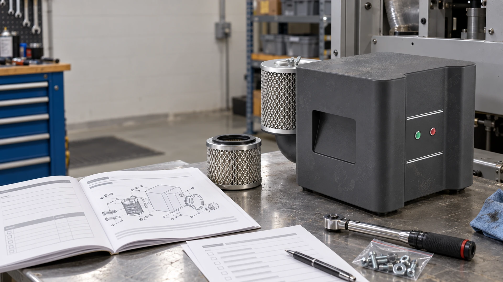
A maintenance checklist copied from another blower can create more problems than it prevents. The filter may be different, the controller may use different alarm codes, and the acceptable temperature or operating limits may not match the installed model.
For the equipment owner, the final manual supplied with the blower should be the technical source. The site checklist is a working version of that manual: shorter, specific to the installed model, and organized around tasks technicians can complete and record.
A dependable model-specific blower maintenance checklist must do more than list filter, air-path and alarm checks. It should state when each task is due, what safe condition is required, what evidence is recorded, who reviews the result and which change or abnormality requires escalation.
Quick Answer: How Do You Build a Model-Specific Blower Maintenance Checklist?
Start with the final manual and the exact blower, controller and accessory model numbers. Extract the manufacturer’s tasks, intervals, operating limits, alarm definitions, replacement parts and safety steps. Convert each item into a checklist row with a trigger, responsible role, required reading or observation, acceptance source, action and record location. Adapt frequency to site conditions only within an approved maintenance process.
The checklist should identify:
- Exact blower and controller models
- Manual revision and document date
- Approved operating limits
- Filter type and part number
- Inspection and replacement instructions
- Air-path inspection points
- Alarm code, meaning, first response, and escalation route
- Lockout and safe-isolation requirements
- Required readings and acceptable comparison baseline
- Person responsible and record location
If the final manual is unavailable, request it from the supplier. Do not replace missing model-specific information with guessed alarm codes or generic service intervals.
Confirm That the Manual Matches the Installed Equipment
Factories often keep several versions of a machine. A manual found in a shared folder may belong to an earlier blower, a different controller, or another voltage configuration.
Before using it, compare:
- Manufacturer and blower model
- Serial number or applicable production range
- Controller model and firmware information, where relevant
- Voltage and electrical configuration
- Filter, silencer, sensor, and accessory models
- Manual revision
- Wiring and control drawings
Record these details at the front of the checklist. A technician should be able to confirm within a minute that it applies to the machine in front of them.
Build the Filter Check Around Condition, Not Guesswork
The inlet filter protects the blower and the process air path. As it loads with dust, system resistance can increase and useful airflow may fall. Depending on the blower and application, temperature, speed demand, power input, or pressure can also change.
The final manual should determine the approved filter type, installation method, cleaning or replacement instruction, and any stated limit. The site can then add inspection frequency based on actual conditions.
A useful filter check records:
- Filter part number and rating
- Date installed or serviced
- Visual condition
- Differential pressure, if monitored
- Blower pressure or vacuum
- Relevant power, current, speed, or temperature trend
- Dust or moisture found around the housing
- Action taken
- Next review date
Do not judge filter condition from appearance alone when the system provides a measurable restriction value. Use the method specified for the installed system.
Cleaning is not always permitted
Some filter elements can be cleaned; others are intended for replacement. Washing, blowing out, or striking an unsuitable element may damage its media or return contamination to the clean side.
Follow the final manual and filter documentation. If the instruction is unclear, ask the supplier before adding a cleaning method to the site checklist.
Site conditions may justify more frequent inspection
A woodworking machine, grinding line, PCB wet process, and clean assembly area do not expose filters to the same conditions. Production changes can also alter dust or moisture load.
The site may shorten the inspection interval when evidence supports it. Do not extend a manufacturer’s limit without a sound technical basis and appropriate approval.
Inspect the Complete Air Path
Replacing a filter does not correct a restriction farther downstream. The maintenance route should follow the air from the inlet to the final process point.
Inspect the items that exist on the actual machine:
- Inlet opening and filter housing
- Silencer
- Flexible hose and rigid pipe
- Elbows, tees, reducers, and manifolds
- Valves, dampers, and bypasses
- Gaskets, clamps, and flange joints
- Air knives, nozzles, diffusers, or vacuum fixtures
- Drains, separators, and moisture traps
- Exhaust route and ventilation openings
Use equipment tags or photographs rather than a vague instruction such as “check pipework.”
Look for restriction and leakage
Restriction and leakage can produce similar complaints at the process: insufficient useful airflow.
A restriction changes the operating point. Leakage allows air to escape or unwanted air to enter a vacuum system. Both can lead operators to increase the blower command or runtime.
Useful evidence includes pressure readings at defined locations, valve positions, filter differential pressure, controller speed, real input power, and the process result. Compare these values with the commissioning baseline whenever possible.
Check for moisture and process contamination
In wet processes, confirm that drains work and liquid cannot flow back toward equipment not designed to handle it. In dusty applications, inspect low points, manifolds, and nozzles where material can collect.
Oil-free air from the blower does not guarantee clean process air. Contamination can enter through the inlet, dirty pipework, damaged filters, or the surrounding environment.
Do not treat permanent bypassing as normal
Relief valves and bypasses may protect or control the system, depending on the design. If a device that was previously inactive now operates continuously, record the change and investigate it.
A new restriction, changed process setting, or incorrect blower command may be shifting the operating point. Adjusting a valve without understanding the cause can hide the symptom while increasing energy use.
Turn Alarm Information into an Actionable Table
An alarm list is useful only when the maintenance team knows what to do next.
For each alarm in the final manual, the model-specific checklist should record:
| Alarm field | Information required |
|---|---|
| Displayed code or message | Exact text shown by the controller |
| Manufacturer meaning | Definition from the final manual |
| Immediate response | Stop, controlled shutdown, or observation as specified |
| Safe first checks | Approved checks that do not require prohibited access |
| Reset condition | Conditions that must be met before reset |
| Escalation | Responsible technician, supplier, or qualified electrician |
| Evidence to save | Time, settings, readings, photos, and operating state |
Do not invent alarm meanings from a similar controller. The same number can mean something different on another product or firmware revision.
Repeated resetting is not troubleshooting
If an alarm returns, preserve the evidence before cycling power or changing parameters. Record what the machine was doing, the blower command, pressure or vacuum, filter condition, ambient temperature, supply condition, and any recent maintenance.
A reset may restore operation, but it does not prove the cause has gone. Repeated alarms require investigation under the final manual and site safety procedure.
Control settings need change records
The commissioning record should contain the approved settings. Maintenance needs a controlled method for recording later changes, including who authorized them and why.
Copying parameters from another machine can create an unsafe or ineffective operating condition. Even identical blower models may serve systems with different pressure, airflow, or control requirements.
Use Trends Instead of Isolated Comments
“Filter okay” and “blower hot” are difficult to audit. A better maintenance record uses consistent inspection points and units.
Depending on the final manual and installed instruments, useful trend data may include:
- Pressure or vacuum
- Airflow
- Filter differential pressure
- Blower command or speed
- Real input power or current
- Ambient temperature
- Temperature at defined equipment locations
- Vibration measurement or repeatable observation
- Alarm count and operating hours
The checklist should state where each reading is taken and under what production condition. A pressure reading at idle cannot be compared fairly with one taken at maximum line speed.
Commissioning values provide the best starting baseline. If no baseline exists, establish one when the blower is known to be clean, correctly installed, and operating at a verified duty.
Set Maintenance Frequency from Three Sources
A practical schedule combines:
- Requirements in the final manual
- Evidence from the operating environment
- Consequences of failure for the process
The manual establishes the technical boundaries. Dust, moisture, high ambient temperature, long hours, or critical production may justify more frequent inspection.
The checklist should also distinguish between inspection, cleaning, replacement, measurement, and functional testing. “Maintain filter monthly” is unclear; “inspect filter condition and record differential pressure” is actionable.
Assign an owner to every task and an approver to every change. When the blower, controller, filter or operating duty changes, review the checklist revision instead of silently editing one row. Keep the previous version and effective date so maintenance records remain traceable.
What Buyers Should Request at Handover
Maintenance quality begins during procurement. Before accepting the blower package, request:
- Final manual for the supplied model
- Controller manual and alarm list
- Approved wiring and control drawings
- Parts and consumables list
- Filter and accessory identification
- Commissioning settings and readings
- Maintenance and inspection requirements
- Warranty conditions
- Technical-support contact and required diagnostic information
Confirm that the documents reflect the delivered configuration rather than a general product family. Include information for external sensors, valves, and interlocks added by the machine builder.
Applying the Guide to a Towwind Energy Saving Blower
Towwind Energy Saving Blowers use high-efficiency BLDC motor technology and may replace traditional ring blowers, regenerative blowers, side-channel blowers, and vortex blowers in suitable applications.
Maintenance instructions, controller alarms, filters, settings, and permitted operating conditions must be taken from the final documentation for the supplied Towwind model. A general blog cannot replace that manual.
Traditional blowers in the 2.2 kW to 5.5 kW range are common candidates for evaluation, but replacement suitability depends on airflow, pressure, operating point, system resistance, controls, electrical supply, and installation conditions.
Towwind Energy Saving Blowers may achieve energy savings of up to 60%–80% in suitable applications. Actual results depend on the original blower efficiency, airflow, pressure, operating hours, system resistance, piping, controls, and installation. Clean filters, a clear air path, and correct settings help preserve the intended operating condition, but maintenance alone does not guarantee a particular saving percentage.
A Practical Site Checklist Structure
The final checklist can be kept short if the references are clear:
| Check | Record | Action source |
|---|---|---|
| Filter | Condition, restriction, service date | Final manual and filter documentation |
| Air path | Leakage, blockage, valve position, moisture | System drawing and commissioning baseline |
| Operating point | Airflow, pressure or vacuum, speed | Approved duty and performance information |
| Electrical condition | Supply and visible connection condition | Final manual and site electrical procedure |
| Cooling | Clearance, ventilation, ambient condition | Final installation requirements |
| Alarms | Exact code, time, load, readings | Model-specific controller manual |
| Settings | Current value and authorized change | Commissioning record and change control |
Keep the full manual available at the machine or in a controlled digital system. Point technicians to the relevant section for detailed disassembly, testing, or parameter work.
The Final Manual Is the Starting Point, Not Shelf Documentation
A model-specific guide prevents two common maintenance errors: applying the wrong instruction to the equipment and reducing a technical check to a box-ticking exercise.
Start with the exact blower and controller documentation. Build filter checks around the approved element and measured condition. Follow the entire air path. Convert each alarm into a defined response and escalation route. Finally, record readings in a form that can be compared with commissioning data.
For help preparing a Towwind maintenance checklist, provide the blower model, controller model, serial information, final manual revision, installed accessories, application, operating hours, site environment, and commissioning readings. Towwind can then support a checklist based on the delivered configuration rather than a generic product description.
Frequently Asked Questions
Can one maintenance checklist be used for every blower model?
No. General inspection principles may be shared, but filter parts, maintenance methods, alarm codes, settings, limits, and safety steps can differ. Build the final checklist from the manual for the exact blower and controller.
How often should a blower filter be replaced?
Use the final manual, filter documentation, measured condition, and site environment. Do not publish or apply a universal interval without confirming the installed filter and operating conditions.
Can I reset a blower alarm and continue production?
Only when the model-specific manual and site procedure permit it and the reset conditions have been met. If the alarm returns, preserve the operating data and investigate the cause rather than repeatedly resetting it.
What should be recorded during an air-path inspection?
Record filter condition, pressure or vacuum, relevant airflow, valve positions, leakage, blockage, moisture, controller speed, input power or current where appropriate, and the process condition at the time.
What information does Towwind need to interpret an alarm?
Provide the blower and controller models, exact code or message, settings, time of occurrence, application, operating state, pressure or vacuum, filter condition, supply information, photographs, and recent maintenance history.