
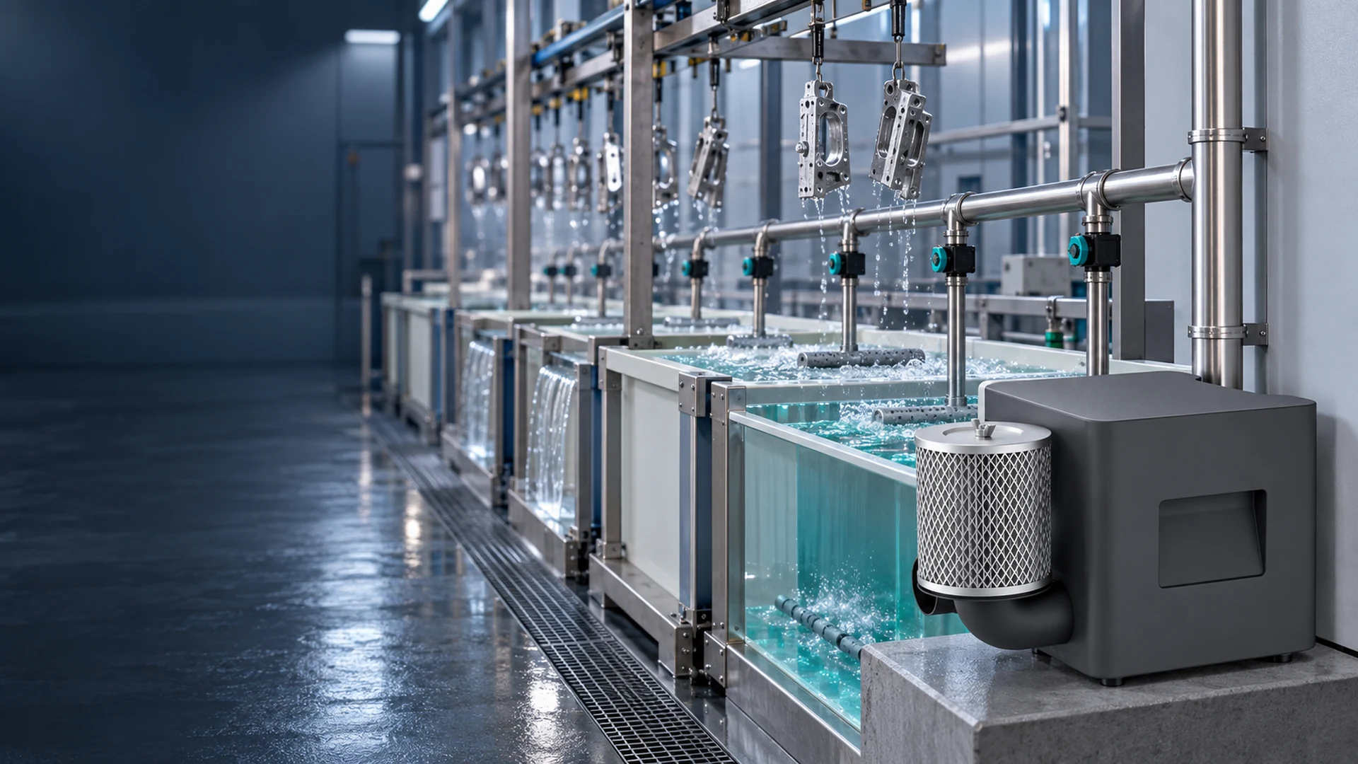
A plating line may have several tanks that use air for agitation, while the same line also has ventilation to capture mist above the baths. Both systems move air, but they do opposite jobs. One supplies air into a selected liquid process; the other removes contaminated air from the work area. Treating them as the same blower application is a costly and potentially unsafe starting point.
For electroplating air supply, first confirm that air sparging is permitted by the specific bath chemistry and process specification. Then define how much air must reach each sparger at its operating pressure, how that air will be distributed and how liquid or corrosive vapour will be kept away from the blower. Only after those conditions are clear should an energy-saving replacement be evaluated.
What Should a Buyer Specify First?
For each tank, specify whether air agitation is approved, which spargers operate together, and the required flow at the pressure imposed by liquid depth and the air path. Add the air-quality requirement, operating hours, site conditions and the process acceptance test. Ask suppliers to mark that duty on the exact blower curve and identify every assumption they made.
Identify Which Tanks Actually Need Air
Surface-treatment lines combine different steps: cleaning, rinsing, plating, conversion treatment and other process stages. Their agitation needs differ. Some baths use air sparging; others use pumped solution movement, workpiece motion or no agitation. The line designer and chemistry supplier should decide which method is appropriate. A blower cannot be specified for every tank just because an existing line has an air header.
Make a tank-by-tank schedule. Record the bath or process stage, whether air agitation is approved, operating temperature, tank depth, sparger type, required mixing result, and when that tank runs. Note whether agitation is continuous, linked to a production recipe or needed only during part of a cycle. If the current method produces acceptable parts, document its operating condition before changing it.
The accepted result is not simply “bubbles visible.” It may be solution movement at the workpiece, uniformity across a long tank, a surface condition or a plating-quality criterion defined by the process team. Too little movement can leave a weakly mixed zone. Too much or poorly directed air can disturb the bath or worsen misting. There is no universal air rate that is correct for every chemistry and tank geometry.
Do Not Confuse Sparging with Fume Extraction
An air-supply blower feeding submerged spargers handles the incoming air stream. A fume-extraction fan handles air that may contain corrosive or hazardous substances. Their materials, placement, protection and design duties are different. An oil-free supply blower is not automatically suitable for acid-mist exhaust. Do not connect it to an exhaust duct unless the exact product and system have been approved for that service.
Air agitation can change mist generation above a tank. That effect belongs in the process and environmental, health and safety (EHS) review. OSHA notes that increased agitation can contribute to mist generation in chromium electroplating, and U.S. EPA guidance also identifies air sparging as a potential source of emissions. Local rules, the bath chemistry and the existing capture system determine what is required. A lower-power air-supply proposal does not override ventilation or exposure-control obligations.
During a retrofit, check whether altered airflow changes the bath surface or the performance of local exhaust. If the process team rejects air agitation for a particular tank, that tank should be removed from the blower duty schedule; it should not be forced into the project to make a common-header design appear simpler.
Match Sparger Layout to Useful Air Delivery
The sparger is where air becomes process agitation. Its hole pattern, length, placement and condition affect distribution. A long perforated pipe supplied from one end may not discharge uniformly along its entire length. Separate tanks on one header may also receive different flows because their depths and branch losses differ.
Give each approved tank or zone a branch on the layout drawing. Show the sparger elevation, liquid depth, pipe route, valve and any check or isolation device. Identify which branches run simultaneously. The blower must provide the combined required flow while overcoming the pressure of the controlling path; pressures from parallel branches are not simply added together.
If a tank has poor agitation only at the far end, examine the sparger and branch before increasing blower output for every tank. A plugged opening, uneven hole pattern or restrictive connection can create a local problem that a larger motor only masks. Technic’s electroplating sparging guidance emphasizes uniform air distribution as a design objective, rather than using total flow as the sole measure of success.
| Tank-by-tank input | Why the supplier needs it |
|---|---|
| Process approval for air agitation | Confirms that air is acceptable for that bath |
| Tank depth and sparger elevation | Defines part of the backpressure |
| Sparger type, length and layout | Affects air distribution and resistance |
| Required or measured branch flow | Sets the simultaneous system demand |
| Pipe, valve and filter arrangement | Adds pressure loss and potential imbalance |
| Operating schedule | Separates continuous and intermittent duty |
| Air-quality requirement | Defines filtration and contamination controls |
| Process acceptance method | Shows whether agitation works without harming quality or EHS controls |
Unknown values should remain marked unknown. If the sparger manufacturer’s data or a reliable field reading is missing, request a test or engineering review rather than guessing pressure from the old blower’s motor plate.
Calculate Pressure at the Working Flow
Air must overcome the liquid head at the sparger, its own discharge resistance, and losses in the supply pipe, fittings, valves and filters. Greater immersion depth generally raises the pressure requirement. Fouling, liquid ingress or a partly shut valve can change it again. The blower’s advertised maximum pressure does not show how much air it supplies at the working pressure.
For a new line, calculate or obtain the expected loss along each relevant air path. For an existing line, measure pressure at the blower and selected branches while the approved tanks operate. State the test conditions and tap locations. A healthy pressure at the blower outlet does not prove the end tank receives sufficient air.
Ask the supplier to mark the required flow–pressure point on the exact proposed model’s curve and state the expected electrical input there. If the line has several operating combinations, check more than one point. How to Compare Existing and Proposed Blower Operating Points explains how to keep field readings and supplier predictions on a common basis.
Specify Air Quality and Protect the Blower
Oil-free air can be valuable where oil carryover would affect the bath or finished surface. Yet “oil-free” does not mean free of dust, moisture or vapour. Confirm the process air-quality requirement with the bath supplier, then choose inlet location and filtration accordingly. If the blower draws from a chemical-laden area, clean internal machinery will not make the inlet air clean.
The air path also needs protection against backflow and liquid entry during shutdown or a power failure. Consider pipe elevation, drainage, check valves or other protective arrangements appropriate to the system, and verify them with the line designer. Do not assume a check valve alone resolves every siphoning or condensate scenario. Components exposed to bath liquid or vapour need material compatibility review.
Keep the blower and controller in a location that satisfies their exact manual’s cooling and environmental limits. The wet, corrosive area near a tank is not automatically a suitable mounting point. Provide access to filters and service connections without putting maintenance staff over open baths. Electrical equipment, cable routing and corrosion protection should be reviewed by qualified site personnel.
Control the Air to the Process, Not to a Fixed kW
Several tanks may not run at once. A shared blower can see very different system resistance when branches open or close. Define the approved operating combinations and how valves and blower output will respond. If adjustable output is proposed, confirm the model’s permitted control range and whether the remaining open branches still receive the required flow at the lower setting.
The process should also specify what happens when air is lost. An alarm at the motor or controller may show that the machine has tripped, but it does not confirm air reaches every tank. Depending on the process risk, a header or branch pressure indication, flow check or quality hold may be needed. Controls and alarms should match the consequences of lost agitation for the actual bath and workpieces.
Keep a baseline record of valve positions, active tanks, pressure and product result. If an operator later changes a valve to fix one tank, that change can steal air from another. A documented distribution plan is more reliable than leaving each branch to be adjusted independently by feel.
Compare Quotations at the Same Scope
Two offers are not comparable if one includes the controller and inlet filter while the other prices only a bare blower. Ask each supplier to return the same items: exact model, flow at the stated pressure, expected real electrical input at that point, controller and alarm interfaces, included accessories, installation conditions, warranty and technical support. Mark any exception to the specified tank schedule.
For a plant owner, the purchase price is only part of the decision. Include expected operating hours, filter and service work, potential pipe or electrical changes, and the cost of a failed process trial. If the old blower still runs, measure its input during representative tank operation before estimating savings. Purchasing can then compare a complete installed proposal instead of two unrelated motor ratings.
Where Towwind Fits—and Where It Does Not
Towwind’s energy-saving blower can be evaluated as a clean-air supply source for suitable, approved tank-agitation duties currently served by a traditional ring, side-channel or regenerative blower. Its BLDC motor technology may reduce electrical input in the right application. Suitability is conditional on the required flow at pressure, run schedule, air quality, environment and controller integration. It is not a blanket recommendation for every plating chemistry, a fume-exhaust fan or a substitute for the site’s EHS review.
To compare energy use, measure the existing blower’s real electrical input with the same tanks operating, the same acceptable agitation result and a known valve configuration. Ask for the proposed package’s input at the matching duty, then verify after installation. If the sparger network, filtration or bath recipe changes at the same time, note those changes rather than attributing the entire power difference to the blower.
The lowest motor rating is not necessarily the lowest total cost. A unit that needs constant throttling wastes pressure; a unit that cannot maintain uniform agitation risks rejects or rework. Purchase decisions should include the blower, controller, inlet protection, pipe changes, installation, maintenance access and any required testing.
Agree the Acceptance Test Before Ordering
The line builder, process owner and EHS team should agree which tanks and production conditions will be tested. Record branch pressures or flows where practical, the blower operating point, real electrical input, sparger pattern and the defined process result. Observe the bath surface and confirm that ventilation and mist-control arrangements remain acceptable under the site’s procedures. Do not declare the retrofit complete because bubbles appear in the easiest tank.
For a supplier enquiry, send the tank schedule, approved sparging methods, depths, sparger and piping drawings, simultaneous operating combinations, air-quality requirement, site environment and existing blower data. Towwind can then review whether a specific blower model fits the clean-air supply duty. Final approval belongs to the plant’s process and safety teams after model-specific documentation and on-site verification.
Frequently Asked Questions
Can air agitation be used in every electroplating tank?
No. Agitation method and intensity depend on the bath chemistry, product and process specification. The line’s process specialist and chemistry supplier should approve air sparging for each tank before a blower is selected.
Is an oil-free blower enough to guarantee clean process air?
No. Oil-free operation does not remove dust, moisture or vapour drawn from the surroundings. Confirm inlet location, filtration and air-quality requirements for the bath.
Can the same blower handle sparging and chemical-fume extraction?
Do not assume so. Clean-air supply and contaminated-air exhaust are different duties with different material and safety requirements. Use only equipment specifically approved for each service by the responsible designers.
What determines blower pressure for tank sparging?
The required pressure includes liquid head at the sparger, sparger resistance and losses through the filter, pipe and valves at the required airflow. Check the governing operating path and the exact blower curve; maximum pressure alone is not a selection point.
—
Editorial notes below — do not paste into the public WordPress article.