
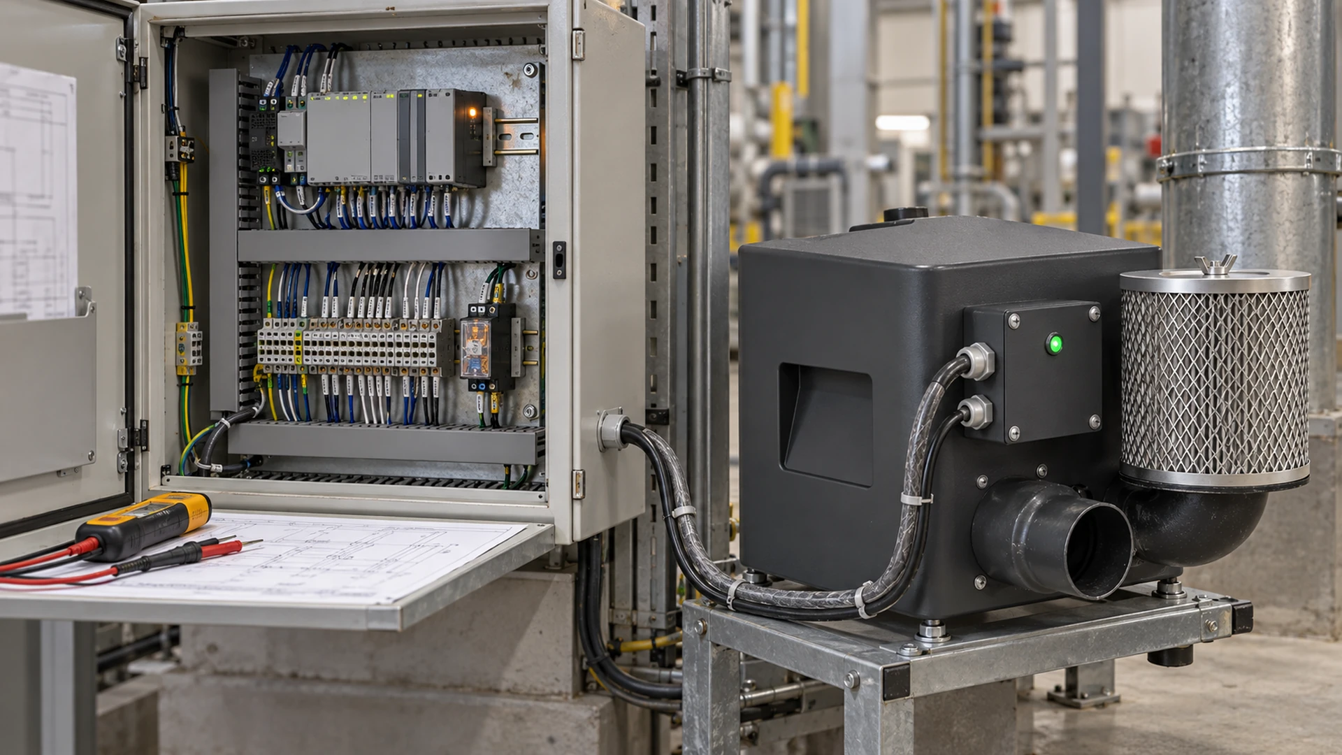
The blower starts from its local control panel, so the installer marks it ready. At the machine’s first production trial, the operator presses Stop and the blower keeps running. The motor and air performance may be fine; the integration is not. A local start test proves only one part of a machine that must also respond correctly to commands, faults and loss of process air.
Blower control and alarm wiring verification means checking the installed machine from end to end: approved drawing, actual terminal, controller setting, PLC input or output, operator display and process response. The point is to demonstrate what happens, not merely confirm that wires have labels. For buyers, a signed test record is more useful than a verbal assurance that “the signals are connected.”
This is a pre-commissioning acceptance guide for a completed machine. It does not prescribe terminal numbers, voltage levels or a method for working on energized circuits. The qualified controls and electrical team must use the final blower and controller documentation, approved machine design and site safety procedures.
First agree what each signal is supposed to mean
A machine may use a start command, stop command, speed reference, run indication, ready status, fault output and a pressure or flow signal. Those names are not interchangeable. “Run” might mean the controller accepted a command, the motor is turning, or a separate process sensor proves air delivery. The definition depends on the actual equipment and program.
Before testing, put the intended behavior beside each signal. State the source, destination, normal state, active state and machine action. If a relay contact is used, the drawing should make clear how the control system interprets its states. If an analog or network signal is used, identify its range, scaling, update behavior and response to a lost signal in the design record. Do not infer these details from a generic product description.
The buyer’s key question is: what machine condition does this signal prove? A controller display saying “ready” does not establish that an air knife has enough pressure at the manifold. If production depends on a minimum air condition, that condition needs an appropriate sensing and interlock strategy of its own.
Compare the as-built machine with the approved drawings
Control problems often begin with small changes between design and assembly: a different controller option, a moved PLC input, a reused cable or a contact wired to a different terminal than the one specified. A test cannot be judged fairly unless the team knows which drawing revision describes the installed equipment.
Confirm the delivered blower and controller identifiers, the approved electrical and I/O schedule, the machine software or parameter revision, and any change notices. Trace each required interface in the documentation before functional testing begins. Physical inspection and continuity or electrical checks must be carried out by qualified personnel under the appropriate safe-work procedure. This blog is not an instruction to probe live terminals.
If the builder substitutes a controller, the test plan should be reviewed again. A status output that was available on one configuration may have a different meaning or need different assignment on another. The supplier should provide the final interface documentation for the delivered Towwind model if a Towwind unit is used.
Test commands in the machine’s real operating modes
An individual start or stop input can work while the full machine sequence is wrong. Define the expected response in automatic, manual and any service mode that the machine actually has. The controls team should demonstrate that the blower starts only when its intended permissives are satisfied and that the process does not begin before the required air condition is available, where the design requires such a condition.
Observe the stop sequence too. Some processes need air for a short period after product feed stops; others need a prompt stop or a controlled shutdown. The correct behavior is an application decision, not a universal blower rule. Record the requested state and the observed state rather than simply ticking “start/stop OK.”
For a variable-speed system, check that the commanded setting produces the expected controller response across the intended range. Document the displayed or measured values used for acceptance. A motor that responds to one manual setting has not proved that the PLC reference is scaled correctly. Confirm any minimum or maximum limits against the selected model and process requirement, not against a setting from another machine.
Prove feedback at the destination, not just at the blower
When a fault or run status changes at the blower, does the PLC see the same state? Does the HMI show the right message? Is the event time-stamped or logged where the buyer expects? A light on the controller is not proof that an operator in another part of the plant will be warned.
Test each important indication from the component that creates it through to the point where someone uses it. If the interface includes fieldbus communication, the design should define what a lost connection means to the machine. If hardwired contacts are used, their behavior when control power is lost should be understood. A contact can be wired neatly and still produce an unsafe or misleading “healthy” indication in a power-loss condition if the logic was not reviewed.
Keep the distinction between equipment status and process proof. A running blower can deliver too little air because a filter is blocked, a valve is shut or a hose is disconnected. If those conditions matter to quality or safety, test the process-sensing arrangement separately and record the intended machine response.
Simulate alarms with an approved test method
Waiting for a real fault during production is a poor acceptance plan. The controls team should agree on safe ways to demonstrate the alarm path for the installed configuration, using approved controller test features or other authorized methods where available. A simulation must be labeled as such in the test record; it may prove the PLC and HMI path without proving the physical fault mechanism.
Prioritize the faults that affect production or equipment protection. These may include a blower fault signal, loss of run feedback, loss of a process-air proof signal or a communication failure, if present in the design. The exact list depends on the machine. For each event, record whether the operator receives a clear indication and whether the machine stops, inhibits feed, enters a reduced mode or follows another approved response.
Do not deliberately obstruct a live blower, defeat a guard or disconnect wiring ad hoc to “see what happens.” Test procedures must respect the delivered equipment limits and site safety controls. If a critical response cannot be demonstrated at the factory, list it as an open site-acceptance item with an owner and planned method.
Check reset and power-return behavior
An alarm is not finished when it appears on a screen. What happens after the underlying condition clears? Can an operator acknowledge it without the machine restarting unexpectedly? Does the blower restart automatically after power returns? Does the PLC retain a start request? These questions deserve a deliberate test because the answer can differ between a local blower controller and the machine program.
The intended reset behavior should be stated in the approved machine design and tested under controlled conditions. The test should distinguish acknowledgement of a message from correction of the fault and permission to restart. If the machine has several control stations, check the relevant ones. Record any auto-restart setting and the final approved value for the delivered model.
Electrical supply and control wiring are related but different reviews. Supply compatibility and protective arrangements should already have been checked before controlled energization. This article focuses on what the machine does with the signals after the electrical team has cleared it for functional testing.
Give the buyer a witnessable test record
Purchasing does not need to choose PLC terminal numbers. It does need to define what evidence will make the machine acceptable. Ask the equipment builder for a short I/O witness sheet that connects each required signal to an observed machine response.
| Test item | What the record should show |
|---|---|
| Start and stop | Command source, selected mode and observed blower and process response |
| Speed reference, if used | Commanded value, observed controller value and operating condition |
| Run or ready feedback | Source definition, PLC/HMI indication and what it actually proves |
| Fault and process-air alarm | Approved test method, indication and machine action |
| Reset and power return | Conditions for restart and observed behavior |
Keep the drawing and software revision with the results. Record who witnessed the test, the date, any simulated inputs, open deviations and the retest result after correction. A result marked “passed” without the signal definition or observed action is hard to audit when the machine reaches the customer.
A practical acceptance rule is to prevent handover while a critical alarm or stop response is unproved. Less critical display-text corrections can be managed as punch-list items if the buyer agrees, but their owner and deadline should still be written down. The classification should come from the machine’s risk and process review, not a generic blog checklist.
Where Towwind fits into the verification
Towwind Energy Saving Blowers may be selected for suitable new machines or replacements of traditional ring, side-channel or regenerative blowers. The control interface required for an installation depends on the exact blower and controller configuration. No universal Towwind terminal mapping, contact state or alarm behavior should be assumed from the brand name alone.
When asking for a Towwind proposal, provide the required operating point, machine control concept, available supply and the signals the machine must exchange. Before commissioning, ask for the final model-specific interface information and have the OEM prove each installed signal against the machine’s approved sequence. If a signal listed in an early quotation is not available in the delivered configuration, resolve the design change before production use.
Any energy-saving comparison belongs to the air-duty review, not the I/O test. Correct alarm wiring can prevent a process failure, but it does not establish an electricity-saving percentage. Compare electrical input only while the old and new arrangements deliver equivalent accepted process output.
Commission only what has been proved
A blower that turns on locally is one component, not a commissioned air system. Before the machine is accepted, verify the command path, the feedback meaning, the operator indication and the action taken when a fault or low-air condition occurs. Keep the test record with the as-built drawings so the site team knows which behavior was demonstrated and which items remain open.
That discipline is especially useful for a production buyer: it turns “wired and ready” into a specific, witnessable result. If the test finds a mismatch, it can be corrected before the machine’s first full shift rather than after a batch has passed through without the air it needed.
Frequently Asked Questions
What should be checked in blower alarm wiring before commissioning?
Confirm what each alarm signal means, where it originates, how the PLC and HMI interpret it, and what machine action follows. Demonstrate the path with an approved test method and record any simulated input separately from a real fault.
Does a blower run signal prove enough airflow?
Not necessarily. It may only indicate that a controller is running or has accepted a command. If the process requires proof of pressure, flow or another result, use a suitable independent process measurement and test the associated machine response.
Should a machine restart automatically when power returns?
There is no universal answer. The approved machine design, risk assessment and delivered controller configuration must define the intended behavior. Test and record it before handover.
Can a buyer accept a blower if the local panel works but PLC feedback is untested?
Only if that feedback is outside the agreed machine scope. If the PLC or operator relies on it for operation, fault response or acceptance, it should be demonstrated at the destination, not inferred from a local display.
Are Towwind control terminals the same on every energy-saving blower model?
Do not assume so. Obtain the final interface documentation for the exact Towwind blower and controller delivered, then verify the installed wiring and machine sequence against that configuration.