
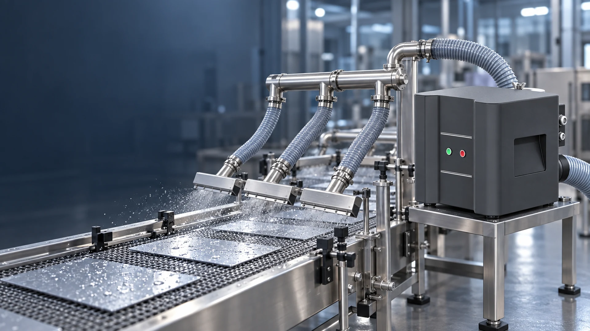
One drying station has two air knives facing opposite sides of a moving product. Another uses a long knife across the conveyor and several short nozzles for edges. The same blower cannot be judged from total slot length alone: each layout presents a different resistance to flow and distributes the air differently at the product.
For a reliable air-knife nozzle layout and blower sizing decision, start at the surfaces that must be dry. Define where air must strike, how much time the moving product spends in the drying zone, and which outlets operate together. Then trace the air path back through each manifold and branch to the blower. The required blower operating point is the flow needed by the complete layout at its combined system pressure, not a maximum-flow figure printed beside a motor rating.
Define Coverage Before Asking for More Air
The first drawing should show the product, conveyor direction and wet areas. Mark the working width, edge geometry, recesses, holes or features that retain liquid. Include the range of product sizes, not only the nominal size used in sales drawings. A nozzle that clears the center of a flat panel may miss the edges when guides or clamps move for a wider product.
Next, show what each air knife is expected to do. One may remove bulk water; another may clear the opposite face; a short nozzle may target an edge where liquid collects. If two devices serve different jobs, do not combine them into one vague “air-knife capacity” requirement. The airflow and pressure at each branch should be specified or left explicitly for testing.
Drying acceptance also belongs on this drawing. Is the goal no visible droplets, no water in a defined feature, or a product condition required by the next process? Avoid a promise that a certain outlet velocity will always produce a dry part. Impact angle, stand-off distance, wetting behavior and line speed affect the result.
Record the Geometry of Every Outlet
The number and arrangement of outlets set the air demand. Record the effective knife length or nozzle coverage, slot or opening geometry, distance to product, angle and feed-port position for each device. A long knife fed from one end may not distribute air exactly like the same knife fed from the center or both ends; the manufacturer’s design and internal manifold matter. Do not assume that equal slot length guarantees equal discharge across the width.
The stand-off distance should be measured at the actual product, including changes in thickness or conveyor position. Increasing distance can spread the jet before it reaches the wet surface. Moving the knife closer may improve impact in one area but create collision, splashback or clearance problems elsewhere. A more powerful blower is a poor substitute for resolving an obviously misdirected outlet.
Nozzle angle should have a reason. The air should push water toward a practical escape path, not drive it into a recess or onto the next product. When outlets face each other, check whether their streams interfere. When they operate in sequence, document which stage handles bulk water and which addresses remaining wet spots. These are layout decisions that determine whether extra air is useful.
For a PCB line, the broader equipment requirements are covered in Blower Requirements for PCB Cleaning and Drying Lines. The principle here applies equally to glass, bottles and other conveyed products: describe the outlet layout before sizing the air source.
Sum Branch Demands at a Common Condition
When several knives operate at once, the blower must supply their combined airflow. However, adding brochure flow numbers can be misleading if each figure was measured at a different inlet pressure. Ask each nozzle or knife supplier for its flow-versus-pressure information at the proposed gap or configuration. The branch demand must be evaluated at the pressure actually available at that branch.
Draw a simple air-path sketch with a branch label for every outlet. For each branch, record its required or predicted flow, inlet pressure, hose or duct route, valves and filter or silencer in the path. The blower’s flow is approximately the sum of the simultaneous branch flows, allowing for leakage and any intentional bypass. The required pressure is determined by the losses along the controlling path plus the pressure needed at the outlet; it is not the sum of the pressure figures for parallel branches.
That distinction prevents a common procurement error. Two air knives each requiring a stated inlet pressure do not automatically require twice that pressure from a shared blower. They do require enough total flow while the branch with the greatest relevant loss still receives its required pressure. The exact duty should be checked against the installed layout and the proposed blower curve.
| Layout item | Record before asking for a blower recommendation |
|---|---|
| Outlet identity | Knife or nozzle type, number and active operating modes |
| Coverage | Effective length, product width and target wet area |
| Opening | Slot or nozzle geometry and any adjustable setting |
| Position | Angle, distance to product and available adjustment range |
| Feed | Port position, manifold design and branch connection |
| Air path | Branch length, diameter, bends, filters, valves and silencers |
| Evidence | Required or measured flow and pressure, with measurement location |
| Acceptance | Drying result and line speed for the relevant product |
If a knife supplier cannot provide the air demand at its intended configuration, mark that uncertainty. A trial, measurement or revised nozzle design may be needed before a blower model can be approved.
Keep Manifold Losses Visible
Air leaving the blower passes through fittings, ducting and manifolds before it becomes a useful drying jet. An undersized branch, sharp transition or long flexible hose can consume pressure that was available on the blower curve. A gauge at the blower discharge may look healthy while a remote knife receives too little air.
Measure or estimate losses across the main supply and each important branch. Record pressure-tap locations, because “system pressure” can mean the blower outlet, branch inlet or knife inlet. Compare like with like. AMCA’s fan-system guidance treats the operating point as the intersection of the fan and system characteristics; the actual installed duct arrangement affects that result.
Where the layout allows it, avoid routing one branch through unnecessary restrictions just to reach a convenient mounting point. If two branches need different flows, use a deliberate distribution strategy and verify it in operation. Closing a valve on the strong branch may help balance a system, but heavy permanent throttling can hide a poor manifold design and add energy cost.
Do not assume a clean-filter test covers the whole service interval. If a filter is needed to protect the blower or process, ask how the expected loading changes pressure and whether the critical branch still receives adequate air. The correct allowance depends on the filter and application; it should be documented, not guessed.
Match the Blower Curve to the Layout, Not the Other Way Around
Once the simultaneous branch requirements and system losses are known, mark the resulting flow–pressure point on the proposed blower’s exact performance curve. Check the operating range at the intended speed or control setting. Catalogue maximum flow and maximum pressure are not normally available together. Also request expected electrical input at the marked duty, not only motor nameplate power.
If the layout has multiple operating modes, mark each relevant point. A narrow product might use only part of a nozzle bank, while a wide product may require all outlets. A variable-output blower may suit that schedule, but the minimum and maximum usable settings must be confirmed from the exact controller and blower documentation. Reducing speed must not compromise drying on the demanding product.
Towwind’s energy-saving blower can be considered for a blower-fed air-knife system when an available model covers the required flow, pressure and duty. Its BLDC technology may reduce electrical input in a suitable application, but no percentage saving follows from the product name. A fair comparison keeps the same nozzle layout and acceptable drying output, then measures real input power under comparable operating conditions. If the air-knife layout changes at the same time, separate the effect of that change from the blower comparison.
Test the Weak Spots, Not Only the Easy Product
Commissioning should include the product or condition most likely to reveal poor air distribution. Check edges, holes, corners and the far end of long knives. Run the line at the agreed production speed, with all relevant outlets active. Record the nozzle positions and filter condition. A slow trial with a clean, flat product may confirm basic operation but not production acceptance.
Where practical, record pressure at the blower outlet and at the controlling knife inlet. A notable difference points to supply-path loss; even pressures at branch inlets do not prove uniform discharge along each knife. Observe the actual drying pattern and check the individual outlet condition for blockage or uneven slot settings. If the process permits it, compare results after a small, documented position adjustment before changing blower speed.
Keep process acceptance separate from an energy test. First establish that the arrangement dries the required product. Then compare power input at an equivalent output and operating schedule. A lower-power system that leaves wet areas is not an energy-saving success.
The cleanest supplier enquiry is a layout drawing with branch labels, product range, line speed, outlet specifications, pipe routes and acceptance condition. Send those details to Towwind with the required or measured flow and pressure where available. The team can assess whether a specific blower has a suitable operating point and identify which uncertainties still need a trial or field measurement.
Frequently Asked Questions
Can I size a blower by adding up all air-knife slot lengths?
No. Slot length does not establish airflow without the opening geometry, inlet pressure and knife design. For multiple outlets, obtain each device’s demand at its intended configuration and evaluate simultaneous branches at a common operating condition.
If two air knives need the same pressure, should I double the blower pressure?
No. Parallel branches need sufficient combined flow, while the blower must overcome the relevant outlet requirement and losses along the controlling path. Branch pressure demands are not simply added together.
Why is the far end of an air knife leaving a wet strip?
Possible causes include uneven internal distribution, an unsuitable feed arrangement, partial blockage, slot variation or poor positioning. Check the knife and its inlet pressure before increasing blower output for the whole system.
Should the drying test use the normal product or the hardest product?
Test both when they represent different required modes. The difficult product checks that the layout can meet its maximum duty; the common product shows how the system operates for most production hours. Record line speed, outlet settings and the acceptance result for each.
—
Editorial notes below — do not paste into the public WordPress article.