
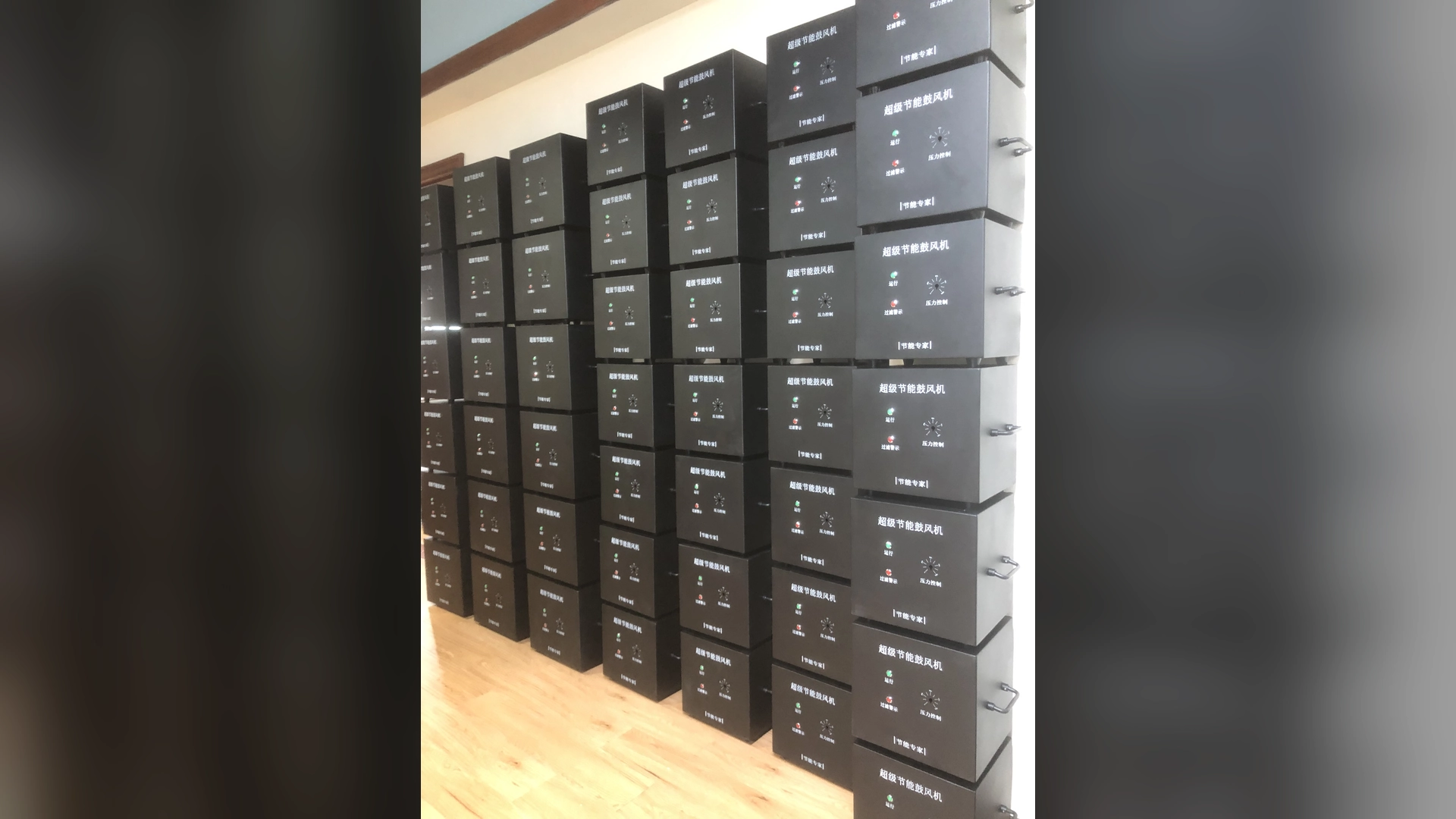
There is no universal ventilation clearance for every high-speed blower. Use the selected model’s manual as the minimum requirement, then confirm that cooling air can enter and hot air can leave without recirculation. Allow access for filters, wiring and removal, and verify temperatures during a representative full-load run with all enclosure panels fitted.
Why One Clearance Number Is Not Reliable
Equipment builders often ask for a single distance between a blower and the cabinet wall. That number can only be model-specific. A gap that works in an open frame may fail inside a sealed, sun-heated or dust-loaded enclosure. Orientation, cooling-air direction, neighboring heat sources and production duty all change the result.
A high-speed blower combines a motor, controller and air-moving section in a compact package. Electrical input that is not converted to useful air power ultimately becomes heat. The process air may also leave the blower warmer than it entered. If that discharge or cooling exhaust returns to the intake, the unit repeatedly breathes hotter air and loses thermal margin.
For that reason, ventilation space is not just empty volume around the casing. It is a complete path for cool air to reach the required inlets and for hot air to escape.
Start with the Final Model Manual
The first source for minimum clearance, orientation and ambient limits is the manual for the exact blower model. A family brochure or a drawing of a similar unit is not enough. Confirm:
- permitted mounting orientation;
- cooling-air inlet and outlet locations;
- minimum distances from walls or panels;
- ambient temperature range;
- altitude or derating requirements;
- enclosure and contamination limits;
- filter-access direction;
- electrical connection and isolation space;
- lifting and removal requirements.
Do not invent a clearance when this information is missing. Ask the supplier for the controlled installation drawing before freezing the cabinet layout. A late change may affect panels, ducts, wiring and machine certification.
Confirm the selected model’s current specification, pressure-flow curve, electrical nameplate and installation requirements before assigning an operating point.
Separate Process Air from Cooling Air
The process inlet supplies air to the application. The cooling path removes heat from the motor and electronics. Depending on the model, those paths may interact or remain partly separate. Designers must know where each begins and ends.
Avoid placing a hot discharge pipe directly in front of a cooling intake. Likewise, do not locate the blower intake beside an enclosure exhaust carrying hot, dusty air. Recirculation can occur even in a large cabinet if openings are badly positioned.
Smoke visualization, safe airflow indicators or temperature mapping can reveal short circuits in the ventilation path. Any test method must be suitable for the facility and must not contaminate the process or enter the blower.
Estimate the Enclosure Heat Load
An enclosure may contain more than the blower. Variable-speed electronics, power supplies, transformers, contactors and nearby heaters add thermal load. Begin with the losses stated by each component supplier. If detailed losses are unavailable, do not assume the full rated motor power is released into the cabinet; obtain suitable data or measure the installed system.
The required ventilation rate depends on heat load, air density, specific heat and the allowable temperature rise. A simplified sensible-heat relationship is:
Heat removed = mass airflow × specific heat × temperature rise
This relationship can support an initial design, but it does not replace the equipment manual or thermal validation. Vent openings, filters, acoustic louvers and bends add resistance. A cabinet fan’s free-air rating will not be delivered against a restrictive filter and louver system.
Use the worst credible operating condition: maximum expected ambient temperature, loaded filters, normal panel configuration and all major components running. For outdoor equipment, include solar gain where relevant. For high-altitude sites, lower air density can reduce cooling capacity and may require manufacturer review.
Place Ventilation Openings to Prevent Recirculation
Cool-air entries and hot-air exits should be separated so discharged heat does not loop back. Natural convection favors low inlets and high outlets, but the blower’s own cooling direction and cabinet layout may call for a different arrangement. Forced ventilation should create a defined sweep through the hot zone rather than a shortcut between adjacent grilles.
Practical layout checks include:
- no wall directly blocking a cooling opening;
- enough open area after guards, mesh and filters are included;
- hot outlet air directed away from the intake;
- no cable bundle filling the intended airflow channel;
- no shelf forming a stagnant pocket above the unit;
- no adjacent machine exhausting into the same intake;
- removable filters on the accessible side of the cabinet;
- drainage where condensation or wash water is credible.
Do not use the process-air inlet as the cabinet cooling solution unless the system was specifically designed that way. Closing a process valve could then remove the assumed cooling flow.
Filters and Acoustic Treatment Consume Ventilation Margin
Cabinet filters protect components from dust, but their resistance rises as they load. An enclosure designed around a clean-filter rating may overheat between maintenance visits. Select filter area from the required flow and allowable pressure drop, then define an inspection or differential-pressure method.
Acoustic louvers and lined ducts also resist flow. They can be necessary for noise control, but sound reduction and cooling must be designed together. A sealed acoustic box may reduce radiated sound while raising ambient temperature around the blower.
Set filter inspection and service intervals from the selected model manual, measured differential pressure, operating hours and site contamination; do not assume a universal calendar interval.
Service Clearance Is Different from Cooling Clearance
A narrow gap may pass cooling air but still make maintenance impractical. The equipment builder should model the tasks technicians will perform, including:
- removing and replacing filters;
- reading labels and indicators;
- accessing terminals and control connectors;
- checking mounting bolts;
- inspecting flexible connections;
- cleaning cooling surfaces safely;
- disconnecting pipes and cables;
- lifting the blower out without dismantling unrelated equipment.
Provide enough space for tools and safe hand position, not merely the component envelope. Keep hot surfaces and rotating equipment guarded. Isolation devices should remain accessible according to the machine’s electrical and safety design.
Also consider replacement over the equipment’s life. If the blower cannot pass through the service opening, a nominally compact installation can create hours of avoidable downtime.
Confirm the Air Path Around Adjacent Components
Clearance on a general arrangement drawing does not show how wiring, hoses and insulation will occupy the space during assembly. Review the installed routing. A flexible hose can expand toward a cooling opening; a cable tray can split the flow; sound insulation can cover a grille.
Heat-sensitive components should not sit directly in the blower’s hot exhaust path. Conversely, the blower should not draw from the exhaust of a drive or heater. Where two machines share an enclosure, simultaneous duty may determine the worst thermal condition.
Pipework needs its own support. Do not use a tight cabinet layout to force a misaligned pipe onto the blower port. Pipe strain, restricted flexible connectors and close elbows can add vibration and system resistance.
Validate the Installation with a Thermal Test
Calculation and layout review are necessary, but a production-representative thermal test provides the final evidence. Run the machine long enough for temperatures to stabilize. Use normal panels, doors, filters, acoustic treatment and adjacent heat-producing equipment.
Record:
- room or outdoor ambient temperature;
- enclosure inlet and outlet temperatures;
- temperature at the blower’s cooling inlet;
- relevant casing or controller temperatures permitted by the manual;
- blower speed, current and measured input power;
- process airflow and pressure;
- filter differential pressure or condition;
- alarm status and any speed derating;
- elapsed time and production load.
Compare results with the final model limits. A ten-minute spin test may confirm rotation and wiring but cannot prove continuous thermal stability. If site ambient during commissioning is lower than the design maximum, use a justified engineering method to demonstrate margin or repeat the test in representative conditions.
Keep the records as a maintenance baseline. Rising enclosure temperature at the same load may later reveal a blocked filter, failed cabinet fan or hot-air recirculation.
Ventilation Space and Blower Selection Are Connected
The blower still must be selected from airflow and pressure at the required operating point. Maximum airflow and maximum pressure are separate curve endpoints, not simultaneous performance. An oversized unit operated inefficiently, or a unit forced against excessive resistance, may create unnecessary heat and noise.
Towwind energy-saving blowers provide adjustable speed for matching suitable duties. Speed control can reduce power when process demand is lower, but it should be commanded from a valid process requirement. Do not reduce speed simply to solve cabinet overheating while allowing drying, cleaning or aeration performance to fall.
A restricted, overheating enclosure cannot be used as the basis for an energy comparison. First verify thermal stability, then compare measured input and equivalent process output.
Information Equipment Builders Should Send
For a model-specific Towwind review, provide:
- required airflow and pressure;
- process-air temperature and composition;
- continuous and intermittent duty pattern;
- supply voltage, phase and frequency;
- expected ambient temperature, humidity and altitude;
- enclosure dimensions and material;
- location of all ventilation openings and fans;
- filters, silencers and louver pressure losses;
- nearby heat loads;
- photographs or CAD views of pipes, cables and access panels.
The proposed model, mounting orientation and interface drawing can then be checked before the enclosure is manufactured. Final ventilation provisions must follow the approved manual and the machine builder’s thermal and safety assessment.
Conclusion
The right high-speed blower ventilation space cannot be reduced to one generic dimension. Cooling depends on a clear air path, total enclosure heat, ambient conditions, filter loading, acoustic treatment and hot-air recirculation. Service and removal space must be planned separately.
Use the exact model documentation, review the complete installed layout and verify the result with a full-load thermal test. For a Towwind application review, send the operating point and enclosure data early enough to change the design before panels, wiring and pipework are fixed.
Frequently Asked Questions
Is there a standard minimum distance around every high-speed blower?
No. Minimum clearance depends on the exact model, cooling path, mounting orientation and installation. Follow the selected model’s manual and validate the complete enclosure under representative load.
Can I install a high-speed blower in a sealed cabinet?
Only if an approved thermal-management design removes the heat and all component limits are satisfied. A simple sealed box can trap heat and cause derating, alarms or shortened life.
Does a larger enclosure guarantee better cooling?
No. A large enclosure can still recirculate hot air or contain stagnant zones. Inlet and outlet placement, forced airflow, filters and internal obstructions matter as much as volume.
How should enclosure ventilation be tested?
Run at representative production load with normal panels, filters and nearby equipment fitted. Record ambient, inlet and outlet temperatures, blower operating data and alarms until temperatures stabilize.
How much service space should be allowed?
Allow the clearance stated in the manual plus practical room to replace filters, access wiring, inspect mounts, disconnect pipes and remove the complete blower safely. Confirm this with the final machine layout.