
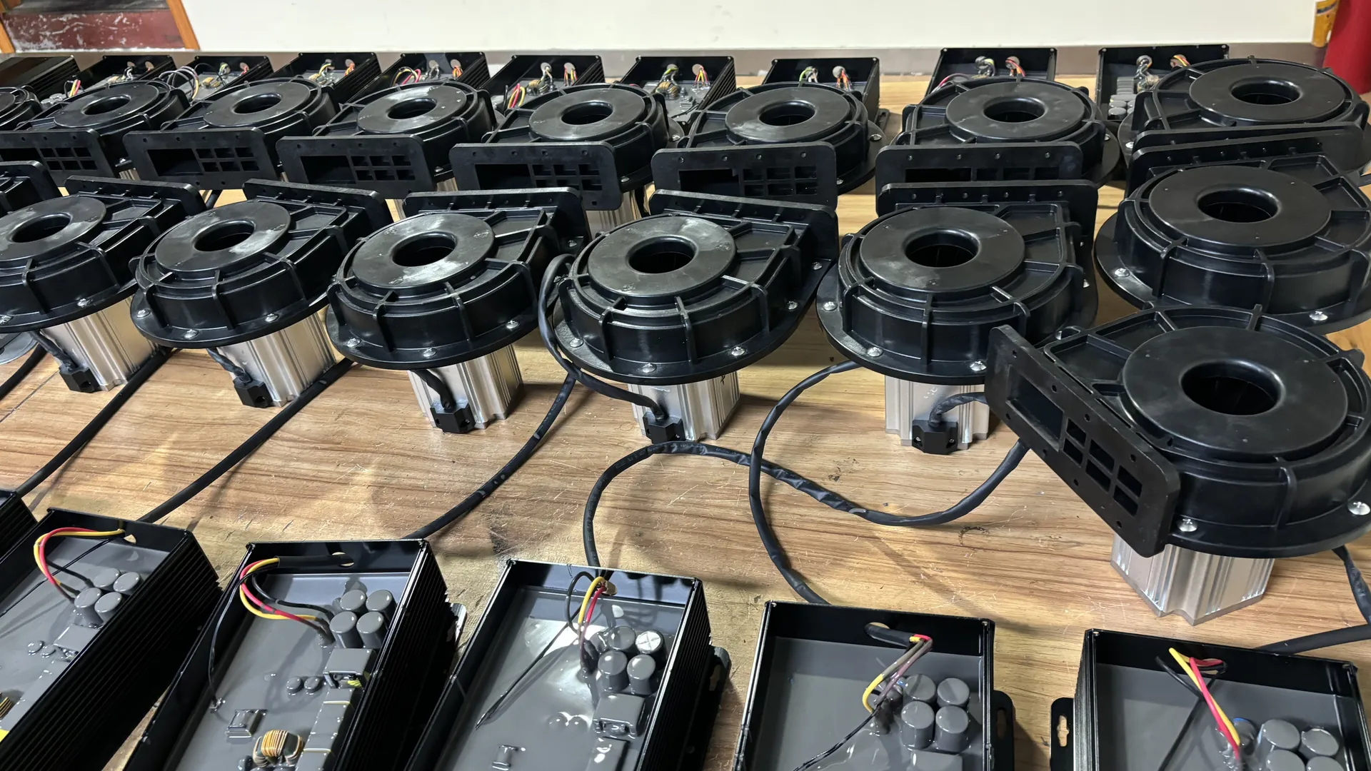
The outlet connection is an interface, not a complete pipe-sizing instruction. Designers must consider actual internal bore, airflow, pipe length, fittings, branches and terminal devices before choosing the downstream diameter.
Quick Answer
Calculate air velocity from the required airflow and actual internal outlet area. Then estimate loss through the adapter, flexible connector, pipe, bends, valves, manifold and terminal device. Use gradual transitions and independently supported pipe where practical.
Do not reduce the outlet merely to increase pressure. A small passage adds resistance and may raise a local static reading while reducing useful airflow. Final selection must use simultaneous pressure and airflow on the exact P-Q curve.
Outlet Diameter Determines Local Flow Area
For a circular passage:
Area = π × internal diameter² ÷ 4
Average velocity = volumetric airflow ÷ area
Use airflow in m3/s and diameter in metres. Divide m3/h by 3,600 to convert it to m3/s.
Because area varies with diameter squared, a small reduction in bore can produce a large velocity increase. Use the narrowest actual internal passage, not the nominal flange or hose description.
High Velocity Raises Loss
Pressure loss in a pipe system generally increases as velocity rises. Tight elbows, valves and abrupt size changes become particularly costly when installed in a high-velocity section.
The exact loss depends on air properties, diameter, length, roughness and component geometry. Use an accepted calculation method or reliable supplier data at the design airflow.
There is no universal outlet velocity limit for every blower. Sound, pressure range, material, route and process requirements all influence the choice.
A Smaller Outlet Does Not Create Free Pressure
Reducing the outlet increases system resistance. The blower operating point moves along its curve, often toward lower airflow and a different pressure. A gauge upstream of the restriction may show a higher value, but that pressure is being spent across the reducer or pipe.
Useful pressure should be measured near the process as well as at the blower. The difference identifies distribution loss.
If an air knife needs more pressure, correct leaks, pipe loss, branch balance and terminal setup before installing a smaller outlet.
A Larger Outlet Does Not Increase the Blower Curve
A larger downstream pipe can reduce loss, particularly on a long route. It cannot make the blower deliver beyond its engineered speed, impeller, casing, motor and controller limits.
Once discharge loss is acceptably low, further enlargement may produce little benefit. Compare at least two practical diameters by calculated loss, installed cost, space and expected operating hours.
Confirm the new operating point after any major pipe change because reduced resistance can change airflow, current and process behavior.
Connection Size and Pipe Size Serve Different Purposes
The blower outlet provides a defined mechanical interface. The distribution pipe carries air over the required route. A gradual expansion may connect a smaller outlet to a larger main when calculations justify it.
Likewise, a branch can reduce after part of the flow has been delivered. Size each section for the airflow it carries rather than forcing one diameter through the complete network.
Confirm final dimensions, flange or clamp type and allowable connection loads from the approved drawing.
Use Gradual Transitions
An abrupt expansion can cause flow separation and poor pressure recovery. An abrupt contraction accelerates air and adds turbulence. A gradual transition usually controls these effects better when space permits.
Transition length and angle should follow sound duct-design practice and supplier guidance. The transition should not obstruct access to the blower, filter, fasteners or controls.
Inspect the internal seam and alignment. A step or protruding gasket can create an unplanned restriction even when the outside dimensions look correct.
Avoid a Tight Elbow at the Outlet
A close-coupled sharp elbow creates a disturbed velocity profile and local loss. It can also transmit pipe force or vibration to the blower connection.
Use a straight section or long-radius bend where the manufacturer and machine layout allow. If space is limited, ask the supplier to review the arrangement instead of applying a generic rule.
Support the elbow and downstream pipe independently. The blower casing should not carry the distribution system’s weight.
Select the Flexible Connector Correctly
A suitable flexible connector can accommodate minor alignment and reduce vibration transmission. It should be short, correctly rated and installed without twisting, stretching or kinking.
Long corrugated hose adds resistance and may flutter at high velocity. A connector that is smaller internally than both the outlet and pipe can become the controlling restriction.
Inspect connectors during maintenance for delamination, leaks, loose clamps and heat damage.
Include Valves and Check Valves
Isolation, balancing and check valves must be sized by their internal flow path and pressure-drop data. A valve labelled with the same nominal size as the pipe may have a smaller bore.
Heavy permanent throttling indicates a mismatch between blower output and process demand. Speed control or a better model selection may reduce the pressure wasted across the valve.
Never remove a required check valve or protective bypass merely to reduce loss. Review its function and select an appropriate low-loss component.
Branches and Manifolds Change the Required Diameter
Before the first branch, the main pipe carries combined demand. After a branch, main flow decreases. A stepped header can reflect this, while a constant-size header may simplify fabrication and future expansion.
Poor manifold geometry can send excess air to the easiest branch and starve remote users. Increasing blower speed then wastes energy at the branches already receiving enough air.
Measure branch pressure and process performance. Correct major layout differences before final balancing.
Terminal Devices Are Part of the Pressure Budget
Air knives, nozzles, diffusers and silencers deliberately or unavoidably consume pressure. Show their requirements separately from pipe loss.
For an air knife, slot length and gap determine outlet area. A widened gap may demand more airflow than the distribution pipe was designed to carry. A contaminated slot may create uneven local performance.
Do not resize discharge pipe without checking the terminal and complete process acceptance criterion.
Outlet Size and Noise
High velocity through reducers, valves and small hose can produce hiss and turbulent sound. Pipe panels and supports may resonate, making normal aerodynamic noise louder.
Correct velocity, leaks, restrictions and loose mounting before adding acoustic treatment. A silencer introduces its own pressure loss and must be selected at the operating flow.
Assess installed sound at a defined duty and measurement position. Outlet pipework, terminals and mounting can change the site result; request exact-model acoustic evidence if noise is material.
Outlet Size and Motor Load
Changing discharge resistance moves the operating point and may change current, real power and temperature. The direction and amount depend on blower design.
Do not assume that a smaller pipe always overloads or unloads the motor. Measure the exact model under approved conditions and compare with its curve and limits.
Qualified personnel should verify voltage and phase current after significant system modification. Stop for repeated alarms, abnormal heat, vibration, smell or noise.
Apply Towwind Product Data Correctly
For a replacement, confirm outlet geometry and the required operating point on the selected model’s released pressure-airflow curve. Separate catalogue maxima do not establish the pressure or flow available through the installed discharge path.
These endpoints are separate. Select the blower and discharge system at the simultaneous required airflow and pressure.
Confirm the selected model’s dimensions, weight and outlet connection on its final drawing before fabricating pipework or support. Family-level dimensions from unreconciled source sheets are not installation evidence.
Energy and Lifecycle Cost
A restrictive outlet system can require more pressure or reduce useful delivery. Correcting loss may allow lower speed, but the energy effect depends on the complete operating point and control method.
Measure real input before and after at equivalent process output. Include operating hours and tariff when calculating annual cost.
Energy and lifecycle cost depend on the existing efficiency, outlet and pipe losses, controls, accepted process duty and running hours. Compare measured input at equivalent output before claiming a saving.
A Practical Outlet Review
- Define required airflow and pressure at the process.
- Confirm actual outlet dimensions and connection standard.
- Calculate velocity at the outlet and every pipe section.
- Estimate loss through reducers, hose, bends, valves and manifolds.
- Inspect branch distribution and terminal demand.
- Provide independent pipe support and service clearance.
- Plot the complete duty on the exact blower curve.
- Commission with airflow, pressure, power, current and temperature readings.
- Verify the accepted process result.
- Preserve the readings as a maintenance baseline.
This process keeps a fabrication detail from becoming a permanent energy and reliability problem.
What Buyers Should Send a Supplier
Provide required airflow and pressure, outlet and pipe internal diameters, total route length, elbows, reducers, valves, flexible connectors, branches, terminal devices, electrical supply, ambient conditions and operating hours.
For a retrofit, include existing measurements at the blower outlet and process point, current or real power, speed setting, filter condition and photographs of the connection.
Ask the supplier to state the proposed operating point, assumed discharge loss and final interface drawing.
Conclusion
Blower outlet size influences local velocity, turbulence, pressure loss, sound and installation loads. A small discharge passage can waste pressure, while an unnecessarily large pipe can add cost without increasing the blower’s tested capability.
Treat the outlet as the beginning of a complete distribution system. Calculate each section at its actual airflow, use appropriate transitions and supports, and verify the operating point during commissioning. That provides useful pressure at the process rather than a higher gauge reading upstream of a restriction.
Frequently Asked Questions
Should discharge pipe match the blower outlet diameter?
Not automatically. The connection must fit the outlet, but downstream pipe size should follow airflow, route, allowable loss, noise, cost and space.
Does reducing outlet diameter increase pressure?
It increases resistance and may raise pressure upstream while reducing airflow. It does not create free useful pressure at the process.
Can I expand immediately to a larger pipe?
A gradual expansion may be appropriate when calculations justify it. Avoid abrupt transitions and confirm the blower’s new operating point.
Why is a flexible hose noisy?
High velocity, corrugations, excessive length, kinks or flutter can create turbulence and vibration. Check internal bore and installation.
What must be measured after changing outlet piping?
Record airflow, blower and process pressure, real power, current, temperature, sound, vibration and process performance at representative duties.