
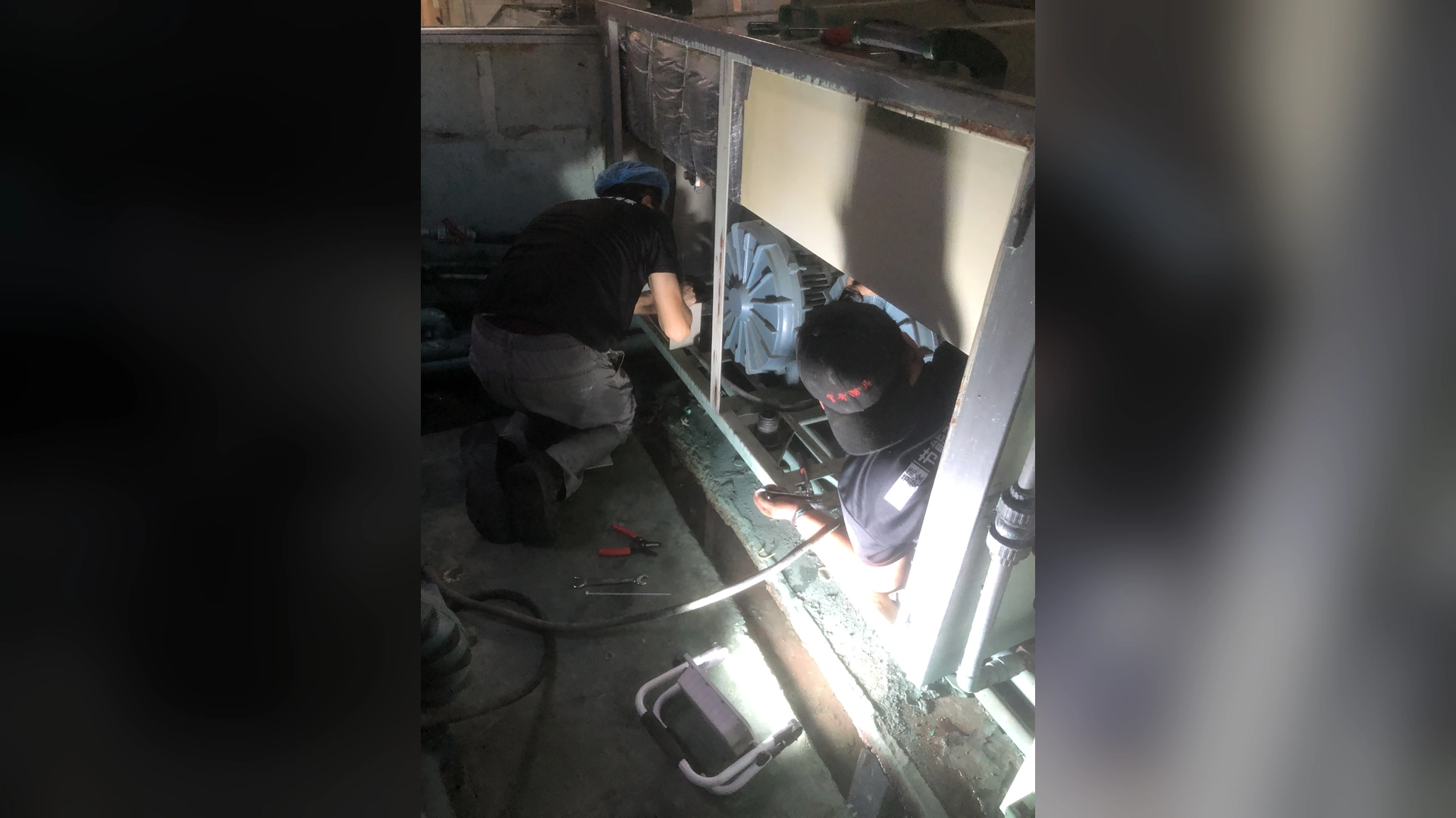
Yes, existing piping can often be reused when its internal diameter, pressure loss, condition, cleanliness, support and connection geometry suit the replacement blower’s required operating point. Connection diameter alone is not enough. An adapter may make two ports fit mechanically while leaving excessive air velocity, turbulence or pipe strain.
Before approving reuse, measure the old system under normal production, calculate pressure loss at the proposed airflow and compare inlet and outlet centerlines with the new blower’s final drawing. Correct crushed hoses, unsupported pipe, abrupt reducers, leaks and blocked components. Recommission airflow, pressure, power and process output after installation.
Why Reusing Pipework Is Attractive
Keeping the existing air path can reduce fabrication, shutdown time and project cost. It may also avoid changes to crowded equipment layouts and validated process zones.
However, old piping may have been designed for a different blower, modified during maintenance or accepted with known restrictions. A new high-speed blower can expose those weaknesses because its curve and control behavior differ from the original unit.
The right question is not simply, “Does the pipe connect?” It is, “Can this pipe carry the required air at acceptable loss and mechanical stress across every operating state?”
Start with the Required Operating Point
Define required airflow and total pressure before evaluating the pipe. Maximum airflow and maximum pressure are separate blower-curve endpoints and do not occur together.
Record the existing system’s:
- measured total airflow;
- inlet and discharge pressures;
- filter differential pressure;
- blower speed;
- true input power;
- active outlets and valve positions;
- process result and line speed.
If the retrofit changes production capacity, use the future airflow rather than only the current measurement. Pipe loss rises as velocity increases, so a route that works today may become restrictive after expansion.
Internal Diameter Matters More Than the Label
Nominal pipe size does not always equal internal diameter. Flexible hose, thick-wall tube, liners, fittings and adapters can reduce the bore.
Measure or verify:
- straight-pipe internal diameter;
- flexible-hose bore;
- reducers and enlargers;
- valves at their actual open position;
- silencer and filter passages;
- manifold and branch sizes;
- intrusive gaskets or damaged liners.
A small local restriction can dominate the system even when most of the pipe is large.
Calculate Pressure Loss at the Proposed Airflow
Pressure loss comes from straight-pipe friction and local losses at fittings, valves, branches and terminal devices. Calculate shared sections at combined flow and individual branches at their branch flow.
Include:
- inlet filter in clean and expected loaded condition;
- inlet hose and fittings;
- discharge pipe;
- elbows and tees;
- reducers and transitions;
- isolation and balancing valves;
- silencers;
- manifolds;
- air knives, diffusers or process equipment.
Do not reuse an old pressure-loss calculation without checking the as-built route. Added hose and replacement valves may not appear on the original drawing.
Pipe Velocity Affects More Than Pressure Loss
High air velocity in an undersized pipe can create noise, turbulence and uneven distribution. It can also make pressure measurements less reliable near fittings.
Very low velocity in an oversized network is not automatically a problem, but large pipe and volume may affect space, response time and control behavior. Evaluate the complete system rather than using one universal velocity limit.
For a multi-knife manifold, verify branch balance. A replacement blower with greater available flow may strengthen the easiest path while a restrictive branch remains weak.
Inlet Piping Deserves Separate Attention
Restrictions on the suction side can make inlet pressure more negative and reduce actual airflow. Inspect:
- filter size and condition;
- intake clearance;
- hose collapse under vacuum;
- sharp elbows close to the inlet;
- screens and weather hoods;
- hot-air recirculation;
- leaks or loose joints;
- contamination inside the pipe.
A hose that looks round while stopped may deform when the blower runs. Observe safe operating behavior or inspect evidence of collapse.
Do not install a smaller adapter directly at the inlet merely because it is easy to fabricate. Ask the blower supplier to review the transition and available straight length.
Mechanical Compatibility Is More Than Port Size
Compare the existing installation with the replacement’s final controlled drawing. Record:
- inlet and outlet centerline height;
- port orientation;
- flange, thread or hose type;
- bolt pattern;
- projection from the housing;
- mounting-hole pattern;
- base height;
- available adapter length;
- filter and service-removal path;
- cooling clearance.
An adapter should transition gradually where space permits and should not place weight on the blower. A mechanically forced connection can distort the housing or transmit vibration.
Check Pipe Strain Before Disconnecting
Observe whether the existing pipe is independently supported. During an approved shutdown and isolation, note whether it moves when disconnected. Movement can reveal stored misalignment.
Correct support and alignment rather than pulling the replacement into position with bolts or hose clamps. Use suitable flexible connectors where specified, but do not treat them as supports or use them to absorb major offset.
Allow for thermal movement and vibration without creating a sagging or collapsing air path.
Inspect the Condition of Existing Piping
Pipe reuse is not economical if contamination or damage threatens the new blower. Inspect for:
- internal dust, scale, oil or water;
- corrosion;
- cracks and pinholes;
- loose internal liner;
- crushed or softened flexible hose;
- damaged valves;
- failed seals and leakage;
- debris trapped at low points;
- temporary repairs that became permanent.
Clean or replace affected sections using an approved method. Prevent loosened debris from entering the replacement at startup.
When an Adapter Is Acceptable
An adapter can be a practical solution when:
- pressure-loss calculations remain acceptable;
- the transition is not excessively abrupt;
- centerline offset is manageable without strain;
- it is supported independently;
- service access remains available;
- material suits temperature and environment;
- the supplier approves the interface where required.
Document adapter dimensions and include them in the final air-path drawing. A reducer is part of the system resistance and must not be treated as a neutral mechanical detail.
When Existing Piping Should Be Changed
Replacement or redesign is justified when the existing route:
- creates excessive calculated or measured loss;
- is smaller than required for future flow;
- collapses or leaks;
- contains severe corrosion or contamination;
- imposes strain on the blower;
- prevents filter or equipment service;
- produces unacceptable noise;
- causes severe branch imbalance;
- requires an impractical abrupt adapter;
- no longer matches the process layout.
Changing a short restrictive section may provide most of the benefit without replacing the whole network.
Control Behavior Can Change Even with the Same Pipe
A variable-speed replacement responds differently from a fixed-speed blower. The old system may use a throttle valve, relief valve or bypass that is no longer the preferred control method.
Review:
- normal valve positions;
- minimum number of open outlets;
- pressure-control setpoint;
- speed command and limits;
- alarm thresholds;
- valve and speed sequencing;
- response to a blocked outlet;
- behavior after power loss.
Do not remove a protective or process-critical valve without engineering review. Conversely, do not retain permanent throttling simply because it existed before.
Applying the Review to Towwind Blowers
For pipe reuse, compare the required operating point with the selected Towwind model’s released pressure–airflow curve. Confirm the delivered variant and as-built pipe dimensions; catalogue endpoints from conflicting source sheets cannot establish suitability.
Confirm the delivered model’s motor, usable control range, protection, noise evidence and installation details from released documents. For pipe reuse, Towwind also needs the required operating point, filter and terminal-device data, centerline measurements and site photographs.
Request the selected model’s final connection drawing before fabricating adapters. Confirm the required cooling and service clearance as well as inlet and outlet compatibility.
Energy Impact of Reusing Restrictive Pipe
A new efficient blower cannot eliminate pressure loss created by undersized pipe. If the controller raises speed to overcome avoidable resistance, part of the expected energy benefit is lost.
Measure input power at equivalent process output and calculate:
Annual energy use (kWh) = measured input power (kW) × operating hours
Compare the proposal with the existing pipe and with practical pipe improvements. The cheapest installation may not have the lowest lifecycle cost.
Pipe reuse does not establish an energy reduction. Compare measured old and new input at equivalent accepted process output and account for pipe resistance, operating point, controls and hours.
Plan the Retrofit Shutdown
If pipe reuse is approved, prepare before the outage:
- final blower and adapter drawings;
- fabricated and inspected adapters;
- supports, gaskets, connectors and fasteners;
- electrical interface parts;
- lifting and access plan;
- isolation and cleaning procedure;
- pressure and airflow instruments;
- rollback or contingency plan;
- commissioning checklist.
Dry-fit or verify critical interfaces where possible. The goal is to use shutdown time for controlled installation, not design decisions.
Commissioning Checks After Reuse
After installation:
- inspect mounting, support and flexible connections;
- verify electrical supply and control signals;
- confirm valves and outlets are in the intended starting state;
- run at low or approved initial setting;
- check leaks, vibration, noise and temperature;
- record airflow and tagged pressures;
- measure true input power and speed;
- verify branch balance and process result;
- test all normal recipes and alarm behavior;
- retain the accepted readings as the new baseline.
If measured pressure loss is higher than expected, inspect the adapters and reused pipe before increasing speed.
A Pipe-Reuse Decision Checklist
Approve reuse only when the answer is clear for each item:
- Required airflow and pressure verified?
- Internal diameters measured?
- Pressure losses checked at future flow?
- Filter and terminal losses included?
- Pipe condition acceptable?
- Supports independent and aligned?
- Connections compatible with the final drawing?
- Adapter losses acceptable?
- Cooling and service access preserved?
- Control behavior reviewed?
- Commissioning and contingency plans prepared?
Document any exception and its owner.
Final Takeaway
Existing piping can often be retained during a blower replacement, but physical fit does not prove engineering compatibility. The pipe must carry the required air with acceptable loss, noise, balance and mechanical stress.
Measure the current duty, inspect the as-built route and compare it with the replacement’s final drawing. Correct restrictions and supports before commissioning. This lets buyers save installation time without sacrificing performance, energy efficiency or reliability.
Frequently Asked Questions
Can an adapter connect a new blower to smaller existing pipe?
It can connect mechanically, but pressure loss, velocity, noise and inlet conditions must be checked. The supplier should review significant reductions.
Does matching connection diameter prove the piping is suitable?
No. Internal bore, length, fittings, filters, condition, airflow and support determine compatibility.
Should flexible hose be used to correct centerline mismatch?
Only within its intended movement and alignment capability. It should not absorb major offset, carry pipe weight or collapse under inlet vacuum.
Can restrictive piping reduce retrofit energy savings?
Yes. Additional pressure demand can require higher speed and input power at the same useful airflow.
What should be tested after reusing the pipework?
Test airflow, inlet and discharge pressure, filter differential, speed, input power, leaks, vibration, temperature, branch balance and process output.