
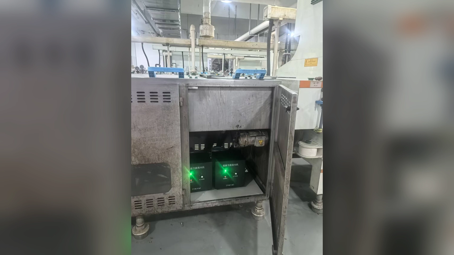
The practical goal is not to make pressure loss zero. It is to deliver the required airflow and pressure at the working point with the shortest, cleanest and least restrictive air path that the machine can reasonably use. That distinction matters: installing a larger blower may hide a restriction, but it also locks the factory into higher operating cost.
Quick Answer
To reduce blower pressure loss, measure pressure at the inlet, blower outlet, main pipe, branch manifold and process connection while the machine runs at a representative load. Clean or replace restricted filters, open undersized valves, remove unnecessary fittings, shorten flexible hose, correct crushed or leaking sections and review pipe diameter. Then rebalance the outlets and verify process results.
Do not change the blower until the required operating point and the system pressure budget are known. A Towwind energy saving blower should be selected from its performance curve at that verified point, not from maximum airflow, maximum pressure or motor power alone.
Start with a Pressure Budget
A pressure budget separates useful process pressure from distribution loss. Begin at the point where air performs the work—an air knife slot, aeration diffuser, cleaning nozzle or drying manifold—and work upstream toward the blower.
Record the required process airflow and pressure first. Next, list the estimated or measured loss through every section: inlet filter, silencer, pipe, bends, isolation valve, check valve, flexible connector, manifold and terminal device. The blower discharge pressure must cover the total at the required airflow.
This method prevents a common purchasing mistake. If a process needs 6 kPa but the installed blower runs near 10 kPa, the difference is not automatically “spare pressure.” It may be consumed by the air path. The location of that loss determines whether the correct action is maintenance, piping work, terminal redesign or blower selection.
Measure the System Under Real Load
Pressure loss changes with airflow, so measurements must be taken while the line is operating normally. A reading with outlets closed or the machine idle does not represent production.
Use suitable gauges or pressure transmitters at stable tapping points. Record pressure before and after each suspected restriction. The difference between two readings is the loss across that section. Where possible, log airflow, blower current or measured input power, speed command, filter condition, product format and line speed at the same time.
Use calibrated instruments and consistent units. For low-pressure air systems, a small gauge error can distort the diagnosis. Avoid placing a pressure tap directly after an elbow or in a turbulent branch if a straighter measurement location is available.
Check the Inlet Before the Discharge Pipe
A dirty inlet filter is one of the quickest restrictions to inspect. It reduces air density and inlet flow, can move the operating point and may increase thermal stress. Compare the pressure before and after the filter, rather than replacing it only by calendar.
Also inspect the inlet grille, silencer and surrounding clearance. Packaging film, dust buildup or a filter element with the wrong area can create a restriction even when the discharge network is sound.
Filter service intervals should follow the final product manual and site conditions. A 30-working-day check or replacement interval may be a useful starting point for some Towwind installations, but a clean indoor line and a dusty process will not require the same schedule. Differential pressure and inspection evidence are better guides.
Remove Sudden Contractions and Unnecessary Fittings
Every abrupt change in flow direction or cross-sectional area creates turbulence. A tight elbow immediately at the outlet, a small reducer, a partially open valve or a manifold with a narrow entrance can consume significant pressure.
Walk the entire route and mark:
- reducers that make the pipe smaller than necessary;
- closely spaced or sharp elbows;
- tees where flow enters the branch abruptly;
- valves that are not fully open;
- check valves with an unsuitable pressure rating;
- kinked, crushed or internally delaminated hose;
- temporary adapters left after commissioning; and
- silencers or terminal devices contaminated by process debris.
Replace abrupt transitions with gradual ones where space permits. Use long-radius bends and full-bore valves. One fitting rarely explains the whole problem, but several small penalties in series can consume much of the available pressure.
Review Pipe Diameter at the Actual Airflow
Small pipe raises air velocity. Higher velocity usually increases friction loss and makes fittings more expensive in pressure terms. However, simply installing the largest possible pipe is not always the best answer. Oversized pipe costs more, occupies more space and may complicate drainage or installation.
Size each section for the airflow it carries. The main pipe before a branch carries the combined demand, while individual branches carry less. Calculate the straight-pipe loss and fitting loss at the design and credible peak flow. Confirm that the blower still operates in a suitable region of its P–Q curve after the network is changed.
Diameter should be based on internal dimensions. Nominal pipe size, hose description and fitting bore may differ, especially when several connection standards are mixed.
Shorten the Route Without Sacrificing Service Access
Long pipe adds friction continuously. If a blower sits far from the machine, shortening the route or relocating the source may reduce required discharge pressure. Yet the shortest geometric route is not always the best installation.
Leave room to remove filters, inspect connections and cool the blower. Keep hot exhaust, process water and dust away from the inlet. A compact arrangement that cannot be serviced will often become restrictive again.
Flexible connectors can isolate vibration and accommodate alignment, but long corrugated hose creates more loss than smooth rigid pipe. Use the necessary flexible length, support it correctly and avoid tight bends.
Find and Repair Leaks
Leaks do not always show as a pressure drop at one component. They create extra airflow demand, which increases loss throughout the upstream system. Inspect joints, hose clamps, unused branches, manifold plugs and seals while the line is pressurized.
Repairing leakage can restore pressure at the terminal and reduce blower demand. After repairs, rebalance the system. Closing leaks changes the system resistance and can move the blower operating point, so current, temperature, pressure and process performance should be checked again.
Balance Branches and Air-Knife Outlets
In a multi-branch system, the easiest path can take too much air while the farthest or most restrictive branch receives too little. Operators may respond by raising blower speed, which wastes energy at the branches already receiving enough air.
Measure branch pressure and verify the actual cleaning or drying result at each station. Correct major pipe differences first, then use balancing devices for final adjustment. Do not use nearly closed valves as a substitute for sensible pipe sizing.
For air knives, inspect the full slot length. An inconsistent gap, internal contamination or poor manifold distribution can cause uneven velocity. Increasing blower pressure cannot reliably correct a damaged or badly adjusted slot.
Separate Process Need from Avoidable Loss
Pressure at the terminal can be useful. For example, a correctly designed air knife needs enough plenum pressure to produce a stable sheet of air. That is different from pressure lost in an undersized hose before the air knife.
This separation helps buyers compare proposals. Ask each supplier to state the proposed operating airflow and pressure, the assumed inlet and discharge losses, and the point at which pressure is specified. Two quotations may appear to offer the same pressure while referring to different locations.
What Pressure-Loss Reduction Means for Energy
Reducing resistance can allow the required airflow at a lower blower pressure or lower speed. The actual electrical saving depends on the blower curve, control method, duty cycle and new operating point. Measure input power before and after the change under comparable production conditions.
Do not calculate savings by subtracting nameplate motor ratings. Likewise, do not assume the maximum pressure and maximum airflow on a datasheet occur together. They are normally separate endpoints of a performance curve.
After correcting restrictions, confirm the new airflow-pressure operating point on the selected blower’s released curve and verify the controller’s usable range for that model. Any energy reduction must be calculated from measured input at equivalent accepted process output and representative operating hours; lower system loss alone does not establish a fixed saving.
A Practical Correction Order
Use a low-risk sequence rather than replacing several components at once:
- Confirm instrument accuracy and production condition.
- Inspect and measure inlet filter restriction.
- Open, clean or repair blocked valves, hoses and terminals.
- Repair leaks and unused branch connections.
- Correct sharp fittings and abrupt size changes.
- Review pipe diameter and long distribution routes.
- Balance branches and adjust air-knife gaps.
- Reset blower speed to the minimum output that meets the process requirement.
- Record the new pressure, airflow, power, temperature and quality result.
This order preserves diagnostic evidence and often finds inexpensive faults before major piping work is approved.
Information to Include in a Supplier Review
Send the supplier a simple marked-up layout showing pipe lengths, internal diameters, fittings, valves, branches and terminal equipment. Include measured pressure at identified locations, required airflow, line speed, operating hours, product changeovers, electrical supply and ambient conditions.
For a Towwind proposal, also confirm voltage, phase and frequency; available installation space; inlet air quality; control and alarm interface; and whether duty is continuous or intermittent. This allows the recommended model and control range to be checked against the real system rather than a generic application label.
Commission and Preserve a Baseline
After changes, run the machine through normal, minimum and peak production modes. Record blower speed command, inlet and outlet pressure, process-point pressure, airflow if available, current or measured input power, bearing or housing temperature, noise condition and process quality.
Save the tapping-point locations and instrument details with the readings. These values become a maintenance baseline. A future rise in filter differential pressure or section loss can then be identified before output falls far enough to stop production.
Conclusion
The most effective way to reduce blower pressure loss is to measure where pressure is being consumed and correct the air path in a controlled order. Filters, undersized passages, unnecessary fittings, long corrugated hose, leaks and poor branch balance are common sources.
Once avoidable loss has been removed, select or adjust the blower for the verified operating point. That approach improves process reliability and gives purchasing teams a defensible basis for comparing energy use, retrofit cost and supplier proposals.
Frequently Asked Questions
What is an acceptable pressure loss in a blower system?
There is no universal percentage. The acceptable loss depends on required process pressure, airflow, pipe layout and lifecycle cost. Each component should have a justified pressure allowance, and avoidable restrictions should be corrected.
Can a larger blower solve low pressure at the process?
It may increase available pressure, but it can also hide a blocked filter, small pipe, leak or restrictive terminal. Diagnose the pressure budget before increasing blower size.
Where should pressure be measured?
Useful points include before and after the inlet filter, at the blower outlet, along the main pipe, before and after suspected restrictions, at branch manifolds and near the process terminal.
Does lower pressure loss always reduce electricity use?
Only if the system is controlled or resized to use the improvement. Measure power at comparable production output and reset speed or control settings after the restriction is removed.
What data does Towwind need to review pressure loss?
Provide required airflow and process pressure, a dimensioned air-path sketch, pipe and fitting details, measured pressures, operating hours, electrical supply, control method and current process results.