
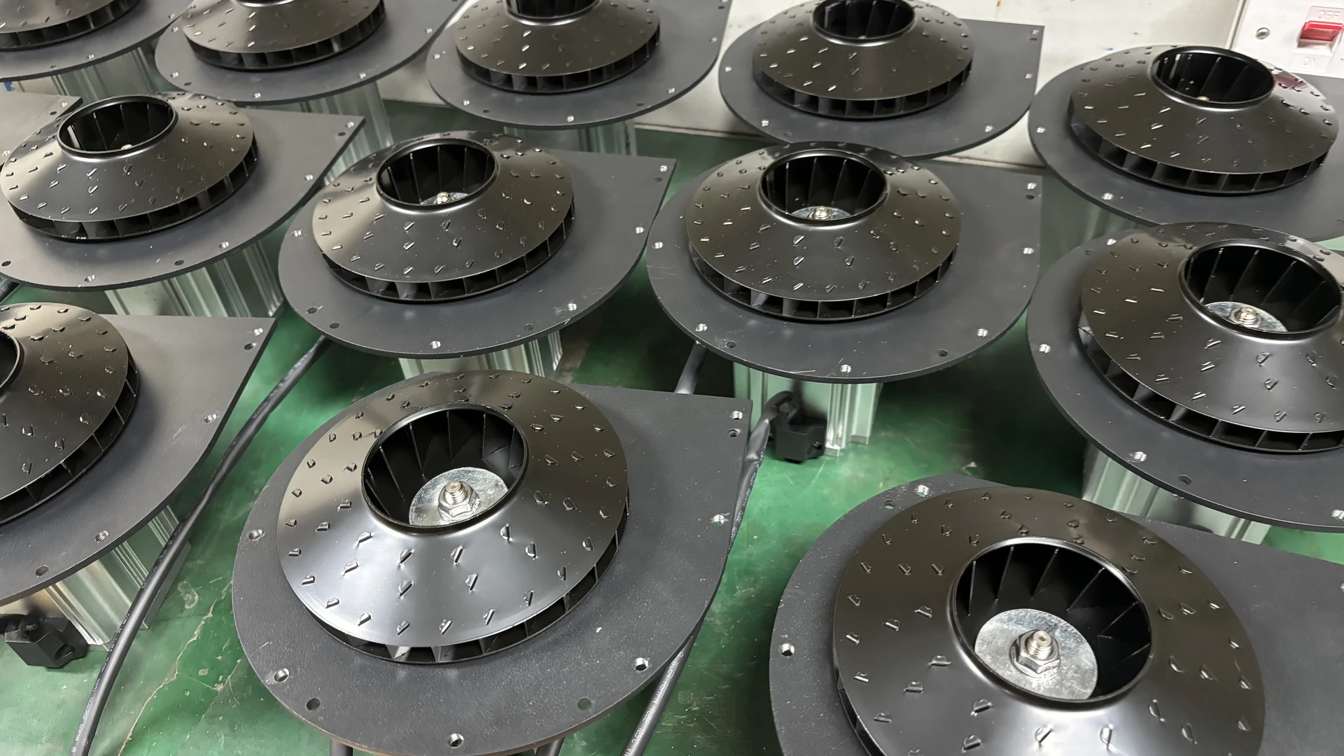
The effect depends on where the angle is measured, blade curvature, impeller diameter and width, speed, clearances and casing geometry. Equipment buyers should therefore compare tested performance at the required operating point instead of asking which blade angle is “best.”
Quick Answer
Blade angle changes the direction and amount of momentum transferred to the air. Depending on impeller type and complete geometry, it can shift pressure, airflow, efficiency and motor load. Backward-curved, radial and forward-curved arrangements have different operating characteristics, but the label alone does not select a blower.
Use the exact P-Q and power curves, permitted operating region and measured input at the required duty. Blade angle is a manufacturer-engineered parameter and should not be bent, ground or adjusted in the field.
Which Blade Angle Is Being Discussed?
An impeller blade has an inlet region, an outlet region and often curvature between them. Engineers may refer to the inlet blade angle, outlet blade angle, stagger angle or a local angle along the blade.
These are not interchangeable. The inlet angle affects how air enters the passage, while the outlet geometry strongly influences discharge velocity and energy transfer. A supplier statement such as “30-degree blades” is incomplete without a reference definition and drawing.
For procurement, detailed proprietary geometry is less important than verified performance and operating limits.
How Blades Transfer Energy to Air
The rotating impeller changes the air’s velocity and direction. The casing or diffuser then converts part of that velocity into static pressure. Blade geometry influences both the magnitude and direction of the exit velocity.
An angle that creates more tangential velocity may support greater pressure, but it can also increase motor load or internal loss. An angle optimized for one flow range may perform poorly at another.
The complete velocity triangles and Euler turbomachinery relationship explain the design in detail, but practical selection still comes back to tested curves at the required operating point.
Backward-Curved Blades
Backward-curved blades lean away from the direction of rotation at the outlet. In many centrifugal designs, they can provide good efficiency and a power characteristic that is easier to manage across part of the curve.
This does not mean every backward-curved blower has the same efficiency or is suitable for every pressure range. Blade count, curvature, width, inlet design, speed and casing all matter.
Ask for the actual efficiency or input-power data instead of accepting the blade category as proof of lower energy use.
Radial Blades
Radial blades extend approximately outward from the centre at the outlet. They can suit applications requiring particular pressure or material-handling characteristics, depending on design.
Their curve, efficiency and power behavior differ from backward- or forward-curved arrangements. The word “radial” does not establish cleanliness tolerance, pressure capability or reliability.
For clean-air industrial drying and aeration, compare the complete product against the process rather than transferring assumptions from material-handling fans.
Forward-Curved Blades
Forward-curved blades lean in the direction of rotation at the outlet. They are used in some fan designs to provide airflow at particular combinations of speed and size.
Power demand can rise significantly across parts of the curve, so motor selection and operating range require careful control. Again, this is a general design tendency, not a conclusion about every product.
The exact manufacturer curve should show pressure, airflow and power together.
Blade Angle and Pressure
Blade exit geometry influences the tangential component of air velocity and therefore the theoretical energy transfer. Yet useful static pressure also depends on slip, internal leakage, diffuser or casing recovery and aerodynamic loss.
A blade angle intended for higher pressure may not deliver that pressure efficiently at every airflow. If the connected system operates far from the design region, recirculation and loss can increase.
Specify simultaneous required airflow and pressure. Maximum pressure near closed flow is not the same as pressure available at production flow.
Blade Angle and Airflow
The blade passage must accept and discharge the required volume without excessive incidence or separation. Inlet angle, blade width and inlet geometry influence how smoothly air enters.
At an unsuitable operating point, air may strike the blade at an unfavorable angle, increasing turbulence and reducing effective flow. A larger outlet angle alone cannot correct an undersized inlet, blocked filter or restrictive pipe.
Measure actual airflow under system pressure rather than comparing free-air maximums.
Blade Angle and Efficiency
Efficiency is the useful air power divided by electrical input, with appropriate definitions and units. Blade angle affects aerodynamic loss, but motor, controller, bearings, clearances and casing also influence total blower efficiency.
The most efficient point is normally a region on the curve, not a permanent property at every flow. A well-designed blower can still waste energy if it is oversized and throttled.
Request input power at the proposed operating point and verify it after installation at equivalent process output.
Blade Angle and Motor Load
Different blade geometries produce different power curves. A motor that is adequate at one duty may overload if the system moves to another region.
This matters when valves open, branches change or filters are serviced. Commission the expected range, not only one normal point. Record current, real input power, pressure, airflow and temperature.
Do not raise controller or overload limits because a modified system demands more flow. Review the curve and motor capability first.
Incidence, Separation and Off-Design Operation
Air should enter a blade passage at a suitable relative angle. When actual flow differs greatly from the design condition, unfavorable incidence can create separation, turbulence, noise and loss.
Off-design operation can result from an incorrect blower selection, a blocked inlet, changed pipe network or heavy throttling. The symptoms may resemble a poor impeller design even though the system moved the operating point.
Compare present readings with the commissioned baseline before blaming internal geometry.
Blade Count, Width and Curvature Matter Too
More blades can guide the flow differently but also add surface and blockage. Wider passages can carry more flow but affect size and loading. Curvature controls how direction changes along the blade.
Clearance between rotating and stationary parts affects leakage. Surface finish and manufacturing consistency affect aerodynamic loss and balance.
Consequently, blade angle should never be separated from these design variables when evaluating performance.
Speed and Diameter Interact with Angle
Blade angle does not create pressure independently of speed. Tip speed is determined by impeller diameter and RPM, while the angle shapes the velocity transfer.
Two designs can use different diameter-speed-angle combinations to meet a similar duty. One may be more compact; another may prioritize a different sound, efficiency or mechanical target.
Compare complete tested blowers. High speed, large diameter or a particular blade label is not evidence of superiority by itself.
Noise and Vibration
Poor incidence and separation can contribute to broadband aerodynamic noise. Blade count and speed affect blade-passing frequency. Installed sound is also influenced by filters, pipe, valves, terminals and mounting.
Compare sound under a defined duty, distance, weighting and background condition. A catalogue noise claim is not evidence of the installed result without the exact model’s test basis.
New scraping, severe vibration or rapidly rising noise requires shutdown and technical review; it should not be treated as a blade-angle optimization issue.
Why Users Should Not Modify Blade Angle
Bending, grinding or welding a blade changes balance, stress, clearance and containment risk. Even a small difference between blades can create high vibration at speed.
Such work also invalidates the tested curve and may affect warranty and safety compliance. Field personnel should never attempt to “increase pressure” by changing the impeller.
If the duty changes, correct system losses or select a blower whose engineered curve covers the new requirement.
Applying Towwind Product Data
Blade angle affects the complete performance curve, but a finished blower cannot be selected from blade geometry or separate catalogue maxima. Use the exact variant’s released curve at the required airflow-pressure point.
These endpoints are separate. The specification does not offer user-selectable blade angles, and no internal geometry should be inferred from the external model data.
Confirm the delivered model’s supply, protection, bearings and usable control range from its final nameplate and manual. Check the actual process duty before comparing alternatives.
What Buyers Should Ask a Supplier
For practical evaluation, request:
- the exact P-Q curve at the proposed speed;
- input power or current across the relevant operating range;
- permitted continuous-duty region;
- motor and controller limits;
- sound test basis;
- inlet and outlet dimensions;
- cooling and filter requirements; and
- commissioning acceptance criteria.
A supplier does not need to disclose proprietary blade geometry to prove performance. Tested, traceable data is more useful than a marketing description of blade angle.
Verify the Complete System
During commissioning, record speed command, airflow, blower outlet and process pressure, real power, current, temperature, noise or vibration and accepted product result.
If site performance differs from factory data, inspect measurement method, air density, filter, pipe loss, valves and terminal setup. Do not assume the discrepancy comes from blade design.
Save accepted values as a baseline for maintenance and later system changes.
Energy-Saving Claims
Any energy change should be measured at equivalent accepted output and representative hours. Do not attribute a whole-system replacement saving to blade angle alone.
Actual savings depend on the complete blower, operating point, motor and control efficiency, existing system, annual hours and process demand. Compare measured input at equivalent airflow, pressure and accepted output.
Transparent measurement is more valuable than attributing efficiency to one hidden design feature.
Conclusion
Impeller blade angle shapes air entry, energy transfer and discharge direction, so it influences pressure, airflow, efficiency and motor load. Its effect cannot be separated from diameter, speed, blade width, curvature, clearance and casing.
For buyers, the correct evidence is the tested curve and power data at the required duty. For users, blade geometry is not an adjustment. Keep the impeller intact, optimize the external air system and choose another engineered model when the operating point changes.
Frequently Asked Questions
Which impeller blade angle is most efficient?
There is no universal angle. Efficiency depends on the complete geometry and operating point. Use tested efficiency or power data for the exact blower.
Do backward-curved blades always use less power?
No. They may offer favorable characteristics in many designs, but motor, speed, casing, duty and system resistance determine actual input.
Can blade angle be changed to increase pressure?
It should not be changed in the field. Modification affects balance, stress, clearance, performance, safety and warranty.
Why does blower efficiency fall away from the design point?
Air may enter or leave the blade passages at unfavorable conditions, increasing incidence, separation, recirculation and other losses.
What should be compared when suppliers do not disclose blade geometry?
Compare exact P-Q and input-power curves, permitted operating range, electrical and environmental limits, sound basis and commissioning results.