
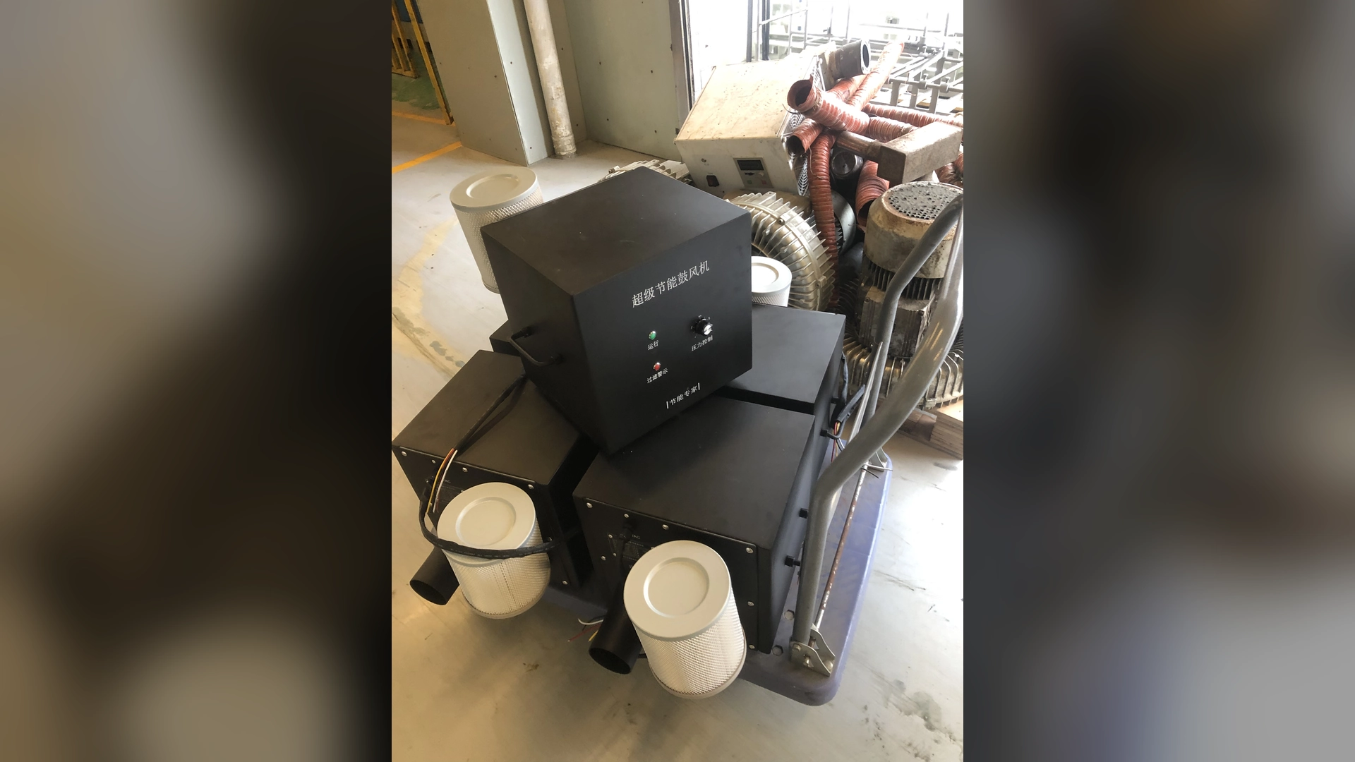
After a blower retrofit, test the installation in stages. First verify mounting, pipe support, connections, electrical supply, control signals, filters, cooling clearance and safety interlocks. Then run at an approved initial setting and check leaks, abnormal noise, vibration, current, pressure and alarms.
Once stable, measure airflow, pressure, speed and true input power at minimum, normal and maximum production states. Confirm the actual process result—such as drying quality or aeration performance—before accepting the retrofit. Keep the final readings and measurement locations as the new maintenance baseline.
Acceptance Must Be Defined Before Startup
Testing is most effective when the team agrees in advance on what success means. Otherwise, installers may focus on whether the blower runs while production expects a particular process result and purchasing expects a certain energy saving.
The commissioning plan should state:
- required airflow and pressure by operating state;
- process acceptance standard;
- measurement method and instrument;
- pressure tap and airflow locations;
- expected speed and electrical input;
- environmental and temperature limits;
- alarm and control functions;
- permitted tolerance;
- responsibility for correcting deviations;
- data required for final handover.
Maximum airflow and maximum pressure are separate curve endpoints. Do not use them together as a site acceptance point.
Review the Retrofit Documents
Before energizing, confirm that the installed equipment matches:
- purchase order and exact model code;
- voltage and phase version;
- final connection drawing;
- electrical and control diagram;
- approved pipe and adapter layout;
- filter and accessory list;
- controller parameters;
- manufacturer installation manual;
- risk assessment and commissioning procedure.
Resolve unexplained differences. A substituted filter, altered reducer or changed controller setting may move the operating point.
1. Mechanical Inspection
With the equipment isolated, inspect:
- blower mounting and fasteners;
- base rigidity and level where required;
- independent pipe supports;
- inlet and outlet alignment;
- flexible connectors for twist, sag or collapse;
- gaskets and joint sealing;
- guards and covers;
- lifting hardware removal;
- filter installation and airflow direction;
- cooling and service clearance;
- foreign material in the air path.
The blower should not be pulled into pipe alignment by its bolts. Correct mechanical strain before running.
2. Electrical Supply Checks
Qualified personnel should verify:
- supply voltage and phase;
- frequency;
- protective devices;
- cable and conductor sizing;
- terminal tightness;
- grounding;
- controller and blower model compatibility;
- insulation or other required pre-start tests;
- emergency-stop integration.
Compare wiring with the final diagram. A 220 V single-phase model and a 380 V three-phase model require different supply arrangements.
Record voltage under load during later testing. On three-phase systems, check applicable phase values and investigate imbalance.
3. Control and Alarm Tests
Test each signal separately before full production:
- local and remote run/stop;
- speed command across the intended range;
- speed feedback;
- ready and running status;
- general fault or specific alarms;
- pressure or flow interlocks;
- valve and blower sequencing;
- emergency stop;
- alarm reset;
- PLC communication;
- behavior after power interruption.
Simulate faults only by an approved safe method. Confirm that the process enters its intended safe state when airflow is lost.
Do not leave alarm testing until after production release. A blower that runs but cannot report a trip is not fully commissioned.
4. Initial Low-Risk Run
Start according to the manufacturer’s procedure at the approved initial setting. Keep personnel clear of rotating equipment, flexible connections and possible debris.
Immediately check:
- correct controller response;
- unexpected pressure rise;
- air leaks;
- loose or moving pipework;
- abnormal mechanical noise;
- excessive vibration;
- current or power behavior;
- cooling-air movement;
- alarms or warning codes.
Stop and investigate abnormal conditions. Do not continue merely to complete a test sheet.
5. Leak and Air-Path Inspection
Inspect joints, unused ports, filter housing, flexible hose and terminal connections. Air lost through leaks may make total blower flow look acceptable while useful process flow remains low.
Verify that valves and dampers are in documented positions. Check that no temporary shipping cover, cleaning cloth or protective plug remains in the inlet or discharge path.
For reused piping, look for crushed hoses, intrusive gaskets and adapter turbulence. Measure differential pressure across suspect components where possible.
6. Airflow Measurement
Measure total airflow using a suitable duct traverse, calibrated flow station or other validated method. Record instrument, location, raw readings, duct dimensions, temperature and units.
If no suitable duct exists, a documented air-knife velocity grid can help verify distribution and compare with the old baseline, but it may not provide the same confidence as a total-flow measurement.
Test every major production mode. Record active outlets, valves and speed with each result.
7. Pressure Measurement
Record pressure type, reference, sign, units and location. Useful measurements include:
- inlet static pressure;
- discharge static pressure;
- blower pressure rise using the appropriate definition;
- filter differential pressure;
- main-header pressure;
- critical branch or terminal pressure.
Use taps in representative locations where practical. High pressure upstream of a restriction does not prove adequate useful airflow.
Compare the installed operating point with the proposed curve, allowing for stated test and environmental differences.
8. Electrical Input and Energy Baseline
Measure true input power rather than assuming nameplate power. Record:
- voltage;
- applicable phase currents;
- true electrical input;
- power factor where relevant;
- speed command and achieved speed;
- operating state and process result.
Current alone is not sufficient for an accurate energy calculation, especially with electronic controls.
For each state:
Annual energy use (kWh) = measured input power (kW) × annual hours in that state
Initial readings establish the baseline. Longer-term verification should cover the real production mix.
Frequently Asked Questions
Allow the system to reach a stable thermal condition under representative load, following the approved test duration.
Record:
- room ambient;
- cooling-air intake temperature;
- cabinet temperature at a defined point;
- controller or motor sensor values available through approved interfaces;
- process-air temperature;
- cabinet fan and cooling-filter condition.
Check for hot-air recirculation and obstructed clearances. Use the final manual for limits; do not invent a universal acceptable temperature.