
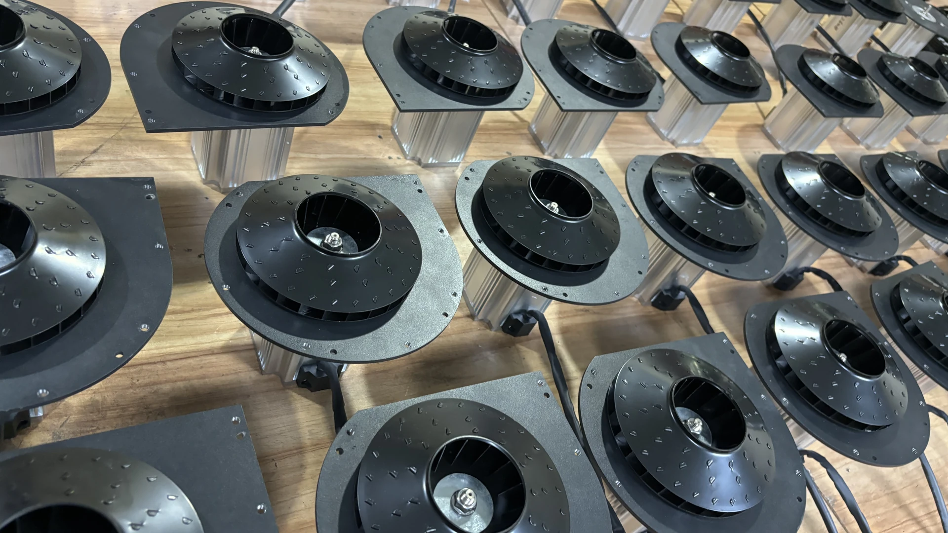
Start by defining where airflow is low and how it was measured. Then work through the inlet, blower, distribution system and terminal device. A larger blower should be considered only after restrictions, leaks, controls and changed process demand have been checked.
Quick Answer
Verify the airflow instrument, units and measurement location. Record airflow and pressure together under representative production. Inspect the inlet filter, valves, leaks, hose, pipe, branches and terminal openings. Confirm speed command, voltage, phase, frequency and rotation where applicable. Finally, compare the measured point with the exact model’s P–Q curve.
Do not use maximum airflow as the expected production flow when the system also requires pressure. Maximum airflow and maximum pressure are normally separate endpoints.
Confirm That Airflow Is Actually Low
A weak drying result may come from poor air knife angle, excessive working distance, incoming water load or faster conveyor speed even when total airflow is unchanged. Before opening the machine, define a process acceptance criterion and measure the air system.
Record product, line speed, active branches, blower command, pressure and process result. Compare these with commissioning data. If no baseline exists, use design documents and supplier curve data cautiously.
Preserve alarm codes and original settings. Follow lockout/tagout and use qualified personnel for electrical work.
Check the Measurement Method
Airflow readings depend on instrument type, duct profile, temperature, pressure and measurement location. A handheld velocity reading at one point in a turbulent outlet does not necessarily represent total volume.
Confirm units: m³/h, m³/min and CFM are easily confused. Check whether quoted flow refers to inlet conditions, standard conditions or another reference. Verify instrument zero and calibration.
Use a suitable straight measurement section where possible, or a recognized traverse method. Document the duct’s actual internal area when converting velocity to volumetric flow.
Inspect the Inlet Filter and Grille
A loaded filter restricts the air entering the blower. Inspect it for dust, oil, water and a collapsed or incorrectly fitted element. Check the inlet grille, silencer and clearance for packaging film or stored material.
Measure differential pressure across the filter while the blower is operating. Replace or clean it according to the final manual. A 30-working-day interval may be a starting point for some Towwind installations, but actual frequency should follow site contamination and measured condition.
Do not remove required filtration to recover flow. Contamination may damage the blower or product.
Look for Inlet Air Recirculation
If hot discharge air returns to the inlet, air density and cooling margin change. Tight enclosures can also starve the inlet even when the filter is clean.
Measure temperature near the actual inlet and inspect ventilation paths. Maintain the service and cooling clearances specified for the final model. Keep process spray and hot exhaust away from the intake.
An enclosure door-open test can provide a clue, but it is not a permanent correction and must be performed only when safe.
Check Valves, Dampers and Bypasses
A partly closed isolation valve or stuck check valve adds resistance. An open bypass diverts flow away from the process. Automated dampers may display a command that does not match their mechanical position.
Compare positions with the commissioning record. Measure pressure before and after a suspected restriction. Restore settings one at a time and remain within manufacturer limits.
Do not close a protective bypass without confirming its purpose. It may be required for cooling, surge avoidance or another operating limit.
Find Leaks and Open Branches
A leak consumes blower flow without delivering useful work. Inspect flexible connectors, clamps, gaskets, manifold ends and unused branches. A damaged air knife or loose end cap can act like a large leak.
Check whether a new machine, cleaning hose or branch was connected after commissioning. Total flow may be similar while each original user receives less.
Repair leaks and rebalance branches, then repeat airflow and pressure measurements because the operating point changes.
Identify Pipe and Hose Restrictions
Undersized pipe, long corrugated hose, tight elbows, abrupt reducers and contaminated silencers increase resistance. A flexible hose may kink, delaminate internally or collapse under suction.
Walk the full route and compare pressure at several points. A large section loss identifies where capacity is being consumed. Use actual internal diameter; nominal pipe labels can hide smaller fitting bores.
Correct avoidable restrictions before increasing blower speed. A larger blower may force air through the problem but creates a permanent energy penalty.
Inspect the Terminal Device
An air knife slot can become contaminated or distorted. Diffusers and nozzles can clog. Alternatively, an air knife gap may have widened, consuming more total airflow while reducing useful velocity and starving other branches.
Inspect the full terminal according to its manual. Record slot or nozzle configuration and compare with commissioning. For drying, verify angle, distance and water exit path.
Do not judge airflow solely by sound. A loud turbulent leak can coexist with poor useful delivery.
Verify Speed and Control Signals
Check the commanded and actual speed, analogue input scaling, production recipe, pressure setpoint, current limit and interlocks. A controller may be capped after maintenance or receiving a signal intended for a different product.
If the selected Towwind controller permits output adjustment, confirm its usable range from the delivered model documentation. Review ramp settings and alarms before changing limits, and verify airflow at the required pressure.
Never bypass protection to obtain more airflow.
Check Electrical Supply and Rotation
Low voltage, a missing phase, poor connection, incorrect frequency configuration or wrong rotation on applicable equipment can reduce performance or cause alarms.
Qualified personnel should measure supply under load and compare it with the installed nameplate. Towwind’s referenced range includes 220 V single-phase and 380 V three-phase versions with 50/60 Hz compatibility; the actual unit documentation governs.
Stop if current, temperature, smell, noise or vibration is abnormal. Preserve the readings for technical support.
Compare the Operating Point with the Curve
The blower delivers airflow where its curve meets system resistance. If system pressure is higher than assumed, actual airflow will differ from a free-air maximum.
Measure airflow and pressure simultaneously and mark the point on the exact released curve at the relevant speed. Separate catalogue maximum-flow and maximum-pressure endpoints cannot explain an installed low-airflow condition.
If the verified required point lies outside the permitted curve after external faults are corrected, the blower may be undersized or the process requirement may have changed.
Distinguish Total Flow from Distribution
Total blower airflow can be adequate while one branch receives too little. Short, low-resistance paths take more flow than long or restrictive branches.
Measure branch pressure and process results. Correct gross differences through pipe layout and diameter, then use balancing devices for final adjustment. Avoid solving one weak branch by raising total output and wasting air elsewhere.
For multiple air knives, inspect manifold distribution across the full slot length, not only inlet pressure.
Consider Changed Production Demand
Higher line speed, wider products, additional nozzles or a different water load can make the old airflow insufficient even when the blower has not changed.
Compare current production with the original design basis. Record each operating mode and required result. If demand genuinely increased, calculate the new pressure-flow point and review pipe, controls and electrical capacity before selecting equipment.
Do not label a capacity increase as a blower failure.
Check for Internal Damage or Wear
If measurement, air path, controls and supply are correct, internal contamination, wear or damage may be reducing performance. Abnormal noise, vibration, heat or smell strengthens the case for escalation.
Do not dismantle warranty-covered equipment without authorization. Send technical support the model, serial number, alarms, operating hours, electrical readings, airflow, pressure, piping information, filter condition and recent changes.
Internal inspection and repair should follow the final manual and qualified service procedure.
A Practical Troubleshooting Sequence
- Record original process and blower readings.
- Verify airflow instrument, units and location.
- Inspect inlet filter, grille and enclosure airflow.
- Check valves, bypasses, leaks and branch changes.
- Measure pressure loss along pipe and hose.
- Inspect air knives, nozzles or diffusers.
- Verify control signal, speed and electrical supply.
- Plot simultaneous pressure and airflow on the curve.
- Review changed process demand.
- Escalate suspected internal faults with evidence.
After correction, repeat the production test and save the readings as a new baseline.
Energy and Replacement Decisions
Do not compare a proposed blower with a faulty baseline. First restore or document the existing system condition, then compare measured input at equivalent process output.
Do not replace a blower solely because airflow appears low. Diagnose duty point, filter and pipe losses, leakage, controls and process demand first; verify any replacement energy difference from measured input at equivalent accepted output and real hours.
An efficient blower cannot compensate economically for a dirty filter, major leak or badly designed terminal. System correction and model selection belong in the same review.
Conclusion
Low blower airflow can originate in measurement, inlet restriction, leaks, valves, piping, terminals, controls, electrical supply, changed demand or the blower itself. A process symptom does not identify which one.
Measure airflow and pressure together, preserve evidence and troubleshoot from the outside inward. This restores useful flow faster and gives buyers a defensible basis if resizing or replacement is truly required.
Frequently Asked Questions
Why is airflow lower than the datasheet maximum?
Maximum airflow is usually a curve endpoint at low pressure. Real piping and terminal resistance move the blower to a different operating point.
Can high pressure and low airflow occur together?
Yes. A restriction or closed outlet can raise pressure while reducing airflow. Measure across system sections to find the cause.
Can a leak reduce airflow at the process?
Yes. The blower supplies the leak as well as the process, so useful delivery and local pressure can fall.
Should I increase speed to restore airflow?
Only after checking measurement, filters, leaks, restrictions, controls and operating limits. A higher setting can hide the fault or overload equipment.
When is a larger blower justified?
When the verified required airflow-pressure point lies outside the existing blower’s permitted curve after correctable system faults have been removed.