
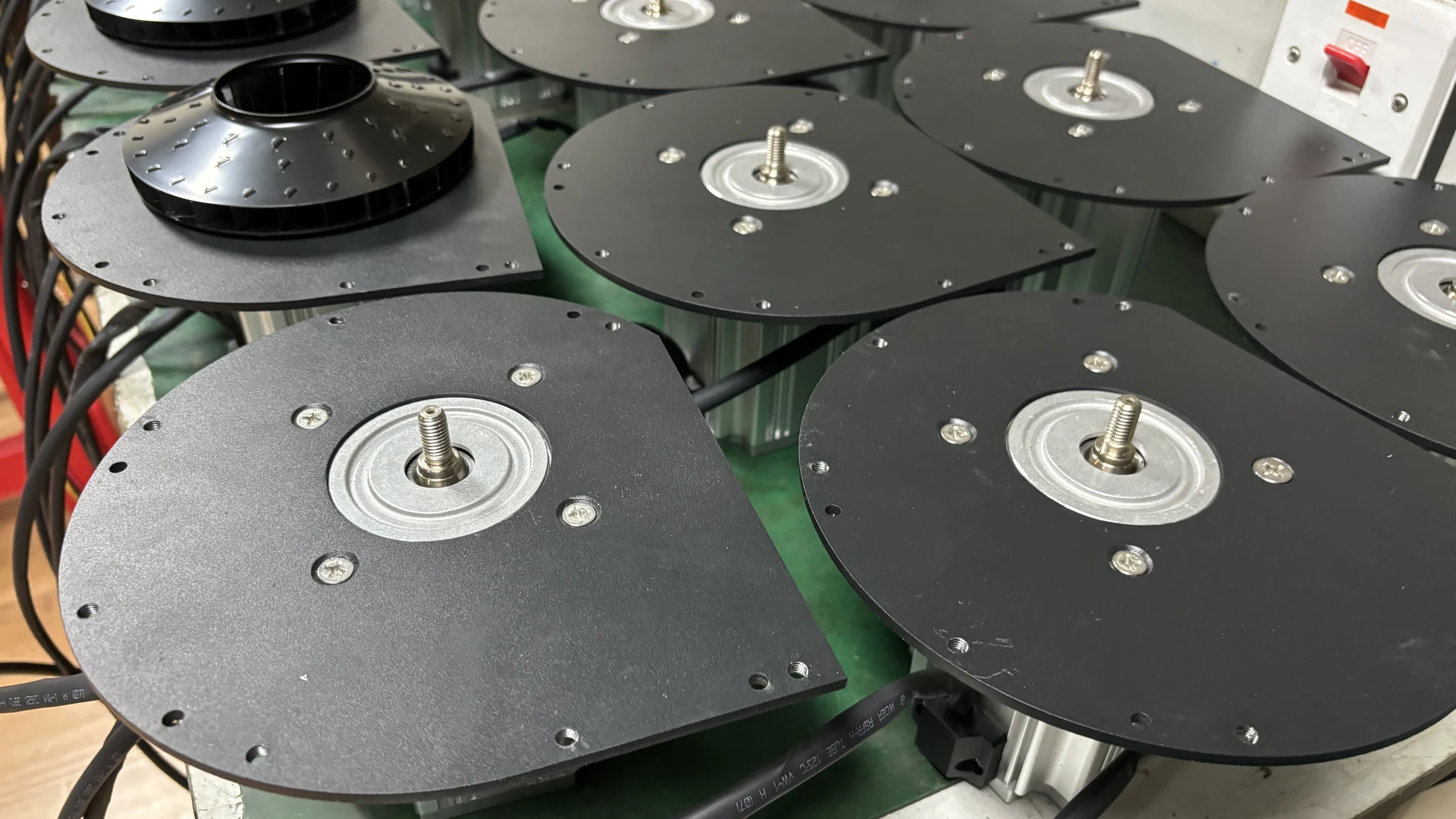
Before increasing speed or ordering a larger blower, preserve the operating evidence and check the air path in a controlled sequence. Many low-pressure complaints come from instruments, filters, leaks, valves or changed production conditions rather than a failed blower.
Quick Answer
Confirm the pressure instrument and measurement point first. Then inspect the inlet filter, leaks, valve positions, blocked or open branches, pipe restrictions, terminal devices, rotation and control command. Compare simultaneous airflow and pressure with the exact model curve. Escalate if alarms, abnormal noise, heat or internal damage are present.
Do not treat maximum airflow and maximum pressure as one operating point. Do not bypass protection or close a process outlet simply to force a higher gauge reading.
Record the Condition Before Adjusting Anything
Write down the blower model, speed command, discharge pressure, process pressure, airflow if available, current or input power, temperature, valve positions, filter condition and active branches. Record product, line speed and the moment the problem began.
Photograph controller alarms and gauge positions if site rules allow. A change made too early can erase the distinction between a system fault and a blower fault.
Follow lockout/tagout procedures before touching filters, guards, piping or wiring. Electrical checks belong to qualified personnel.
1. The Pressure Reading Is Wrong
A damaged gauge, blocked pressure tap, leaking tube or incorrect zero can show low pressure even when the process receives normal air. Digital sensors can have wrong range, scaling or engineering units.
Compare the reading with a calibrated reference at the same point. Inspect taps for water or debris. Confirm whether the value is gauge, absolute or differential pressure and whether the controller converts it correctly.
Avoid taking a static reading directly in highly turbulent flow when a better measurement location is available.
2. Pressure Is Measured at the Wrong Location
Pressure at the blower outlet is not the same as pressure at an air knife or remote branch. Piping, filters and valves consume pressure between those points.
Mark every tapping location on a layout. Measure before and after suspected restrictions while production is running. The difference shows the pressure loss across that section.
A healthy outlet reading with low process pressure points toward distribution loss. Low outlet and process readings require further checks of inlet, control, blower and system demand.
3. The Inlet Filter Is Restricted
A loaded inlet filter limits air entering the blower. It can reduce available airflow and affect pressure, temperature and current.
Inspect the element and measure differential pressure under load. Clean or replace it according to the final manual and site conditions. A 30-working-day interval may be a starting point for some Towwind installations, but dusty processes may need more frequent attention.
Do not run without required filtration. Contamination can damage the blower or product and may invalidate the diagnosis.
4. The System Has an Air Leak
A loose clamp, split hose, failed gasket or open unused branch allows air to escape before it reaches the process. The blower supplies extra flow, while pressure at the intended outlet falls.
Inspect joints, flexible connectors, manifold end caps and branch plugs. Use an approved leak-detection method suitable for the pressure and environment. Repair leaks, then remeasure because the operating point will change.
Leaks can also be internal to process equipment, such as an air knife end seal or damaged manifold.
5. A Valve or Damper Is in the Wrong Position
An isolation valve may be partly closed after maintenance. A bypass may be open, sending air away from production. A check valve may be installed backward, stuck or too restrictive.
Compare actual positions with the commissioning record and control display. Do not rely only on a handle direction if the linkage can slip.
Change one item at a time and remain within permitted operating limits. Never defeat a protective bypass without manufacturer review.
6. A Branch or Terminal Is Blocked—or Too Open
A contaminated air knife slot, clogged diffuser or blocked nozzle can reduce local performance and change system pressure. Conversely, a broken terminal or newly opened branch can lower header pressure by demanding too much flow.
Inspect every active outlet. On a multi-branch system, isolate or test branches only under an approved procedure. Compare pressure as each user changes state.
An air knife with an enlarged or uneven gap may consume more airflow than the original design, leaving insufficient pressure for other knives.
7. Pipework Is Restrictive or Damaged
Undersized pipe, long corrugated hose, tight elbows, abrupt reducers and contaminated silencers consume pressure. A flexible hose can kink or collapse; a pipe can be crushed during nearby work.
Measure along the route to find the section with abnormal loss. Compare with the clean-system baseline or pressure budget. Correct the restriction rather than permanently raising blower speed.
Pipe diameter should be based on internal bore and actual airflow. A nominal size can hide a smaller fitting passage.
8. The Blower Speed or Control Signal Is Limited
The controller may receive a low command, incorrect analogue scaling or a production recipe intended for another product. A pressure-control setpoint, current limit or alarm response may cap output.
Record commanded and actual speed where available. Verify signal range, wiring, recipes, ramps and interlocks against the final manual and controls documentation.
Towwind energy saving blowers provide 0–100% adjustment, but the safe and useful setting must match the selected model and application. Do not bypass limits to diagnose a capacity problem.
Frequently Asked Questions
Incorrect phase sequence on applicable three-phase equipment, low voltage, missing phase or poor connections can reduce performance or trigger protection. Recent wiring work is an important clue.
Qualified personnel should confirm voltage, phase, frequency, terminals and rotation using the manufacturer’s procedure. Towwind’s referenced range includes 220 V single-phase and 380 V three-phase variants with 50/60 Hz compatibility; the installed nameplate is authoritative.
Stop if abnormal current, smell, heat or repeated alarms are present.