
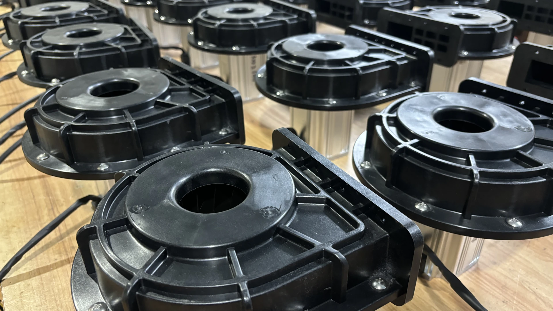
A suitable blower must deliver the specified air at tank depth through the installed spargers and piping. It must also be located and protected so fumes, mist and liquid do not damage the package or contaminate the process. Whether air agitation is appropriate at all must be confirmed by the process owner and chemical supplier.
Quick Answer
Select an electroplating aeration blower only after the process engineer defines required airflow, acceptable air quality and compatible agitation method. Calculate total pressure from solution depth, sparger loss, piping, valves and filters. Check the simultaneous airflow-pressure point on the exact blower curve.
Then review chemical exposure, inlet location, pipe materials, backflow prevention, electrical environment, control and redundancy. A lower-power blower is not a valid upgrade unless it maintains the approved process result and does not introduce contamination or safety risk.
Confirm That Air Agitation Is Permitted
Not every plating bath should be aerated. Air can change oxidation conditions, increase mist, alter additive behavior or affect deposit quality. Some processes use mechanical circulation, eductors or pumped solution movement instead.
The process owner should specify which tanks use air, when it operates and the required distribution. Consult the chemical supplier for bath-specific restrictions. Do not infer suitability from another line using a similar-looking solution.
Define the accepted result in process terms: coating appearance, thickness distribution, adhesion or other controlled quality measures. Airflow is an input, not the final acceptance criterion.
Define the Airflow Distribution
Document tank dimensions, normal and maximum liquid level, sparger type, hole or diffuser layout and active zones. Identify whether several tanks share one header and which combinations can operate simultaneously.
Uniform distribution matters. The closest sparger can receive most of the air while a remote tank appears weak. Balanced header design, branch sizing and controlled valves can improve distribution. Record accepted valve positions; uncontrolled adjustment can change both agitation and total system resistance.
Use sparger supplier or process design data for airflow. If the requirement is based on field experience, document tank level, branch configuration and the quality result. Avoid converting “visible bubbling” into an unsupported engineering value.
Calculate Required Pressure
The blower must overcome:
- hydrostatic pressure from the maximum liquid depth above the outlets;
- sparger or perforated-pipe resistance;
- friction in main and branch piping;
- fittings, valves, filters and protective devices; and
- any difference in elevation or shared-header condition.
Calculate these losses at the total simultaneous flow. For a retrofit, measure discharge and branch pressure while recording liquid level, active tanks, valve positions and sparger condition.
A rise in pressure at similar operation may indicate deposits, crystallization, a closed valve or blocked sparger. Falling pressure with weak agitation can indicate leakage, an open branch or blower deterioration. Baseline readings shorten diagnosis.
Check Pressure and Airflow Together
Maximum airflow and maximum pressure are separate endpoints of a blower curve. An open-air flow number does not show how much air reaches a submerged sparger. Likewise, a maximum pressure number does not prove sufficient flow at working depth.
Plot minimum, normal and maximum tank combinations on the exact model curve. Confirm the points remain in the permitted range and include a justified allowance for normal system change. Do not add excessive margin for unknown sparger condition; inspect or test the system instead.
If the required pressure exceeds the model range, select another technology. Restricting the process requirement to make a smaller blower appear suitable is not an acceptable energy project.
Towwind Models for Preliminary Screening
Request the released curve, electrical and environmental data and final installation drawing for the exact proposed model. Compare tank depth, sparger and piping losses with usable flow at pressure; reject an unverified match.
Confirm the selected model’s control range, electrical supply, environmental rating, certification, noise and dimensions from current released documentation. Adjustable output does not replace a verified pressure-flow match.
Confirm the tank duty on the released exact-model curve and reject a candidate if depth plus losses exceed verified capability. Check the final port and installation drawing before fabricating piping.
Protect the Blower from the Process Environment
Plating lines can release corrosive mist and vapor. Locate the blower inlet where it draws suitable air and protect the package from splash and washdown. Verify chemical resistance and hazardous-area suitability for the exact supplied equipment.
Review whether the area is corrosive or classified and select electrical and mechanical equipment accordingly. This assessment belongs to the site and qualified designer. If Towwind’s delivered model is not approved for the environment, relocate it or choose appropriate equipment.
Keep cooling passages unobstructed. Provide service clearance without exposing technicians to open tanks or unsafe access. Route exhaust noise and heat so they do not create another workplace problem.
Prevent Backflow and Cross-Contamination
If blower pressure disappears, liquid may move back through submerged piping. Use engineered check, isolation, high-loop, drain or break arrangements as appropriate to the chemistry and layout. Test shutdown and power-loss behavior during commissioning.
Shared headers can also connect tanks unintentionally. Pressure differences or a stopped branch may allow vapor or liquid migration. The piping design must prevent incompatible chemistries from communicating through the air system.
Select pipe, valve, seal and sparger materials for the actual solution and temperature. The blower specification alone does not establish compatibility of downstream components.
Air Quality and Contamination Control
The blower draws ambient air. Dust, oil mist, corrosive aerosol or nearby exhaust can enter the process if inlet location and filtration are poor. Define the acceptable air quality with the process owner.
Install and maintain appropriate filtration without creating uncontrolled restriction. Record filter condition during baseline and acceptance testing. A loaded filter reduces air, while removing filtration to recover pressure can expose the bath and blower to contaminants.
Set filter service frequency from the environment, pressure trend, risk assessment and final manual.
Control Around the Plating Recipe
Tank combinations and work loading can change. Adjustable output may reduce energy when fewer tanks operate, but every setting must preserve the process requirement. Define approved recipes, minimum command and valve states.
Integrate blower status and alarms with the line. If air agitation is essential during a process step, the control system should prevent unrecognized operation without it. Define the response to signal loss, protective trip and power recovery.
Do not use dissolved-gas or quality assumptions as feedback without validated sensors and process logic. Many plating results are confirmed after processing, so conservative limits and good records are important.
Energy Verification
For tank aeration, compare measured input only after both systems meet the approved plating recipe, air-distribution and product-quality criteria. Existing throttling, pipe loss and duty cycle determine the project-specific result.
Measure complete blower-package kWh while the old and proposed systems serve the same tanks, liquid levels, airflow requirement and accepted process. Include idle periods and changing tank combinations. Rated motor power is not actual energy use.
Annual energy equals measured average input for each mode multiplied by annual hours in that mode. Apply the site’s tariff to the verified difference. Treat quality, chemical consumption, maintenance and downtime separately; an energy saving is invalid if coating quality or bath control deteriorates.
Procurement and Commissioning Checklist
Before ordering, provide:
- bath type and confirmation that air agitation is permitted;
- tank dimensions and liquid-level range;
- required airflow and distribution;
- sparger design and pressure loss;
- pipe layout, materials, valves and simultaneous tanks;
- required pressure-flow points;
- inlet-air and chemical-environment assessment;
- backflow and cross-connection controls;
- voltage, phase, controls and alarms; and
- product-quality and energy acceptance methods.
Commission under a representative tank combination. Record pressure, setting, power, active branches, liquid level, temperature and process result. Test power loss, restart, check devices and alarm logic. Retain these records as the maintenance baseline.
Final Recommendation
An energy saving blower can serve compatible electroplating tank aeration when the process approves air agitation and the calculated pressure-flow duty lies within the model curve. The installation must protect both the blower and the bath from chemical exposure, backflow and contamination.
Send Towwind the tank, sparger, piping, pressure, flow, environment, voltage and control data. A responsible proposal should identify assumptions and decline duties outside the product’s pressure or environmental limits. That protects coating quality and gives procurement a credible energy comparison.
Frequently Asked Questions
Can every electroplating bath use air agitation?
No. Bath chemistry and process requirements determine suitability. Confirm with the process owner and chemical supplier before designing the air system.
Why is liquid depth important?
The blower must overcome hydrostatic pressure from the liquid above the sparger, plus sparger, pipe, valve and filter losses.
Can one blower supply several plating tanks?
Yes, if simultaneous demand, balancing, chemical compatibility, backflow and cross-connection risks are engineered. Shared headers require careful control.
Does an ingress rating prove chemical resistance?
No. An ingress rating alone does not establish resistance to plating chemicals, suitability for classified areas or direct washdown. Check the released model data and site assessment.
How should energy savings be measured?
Compare complete package kWh under equivalent active tanks, liquid levels, process airflow and accepted coating results over representative operation.