
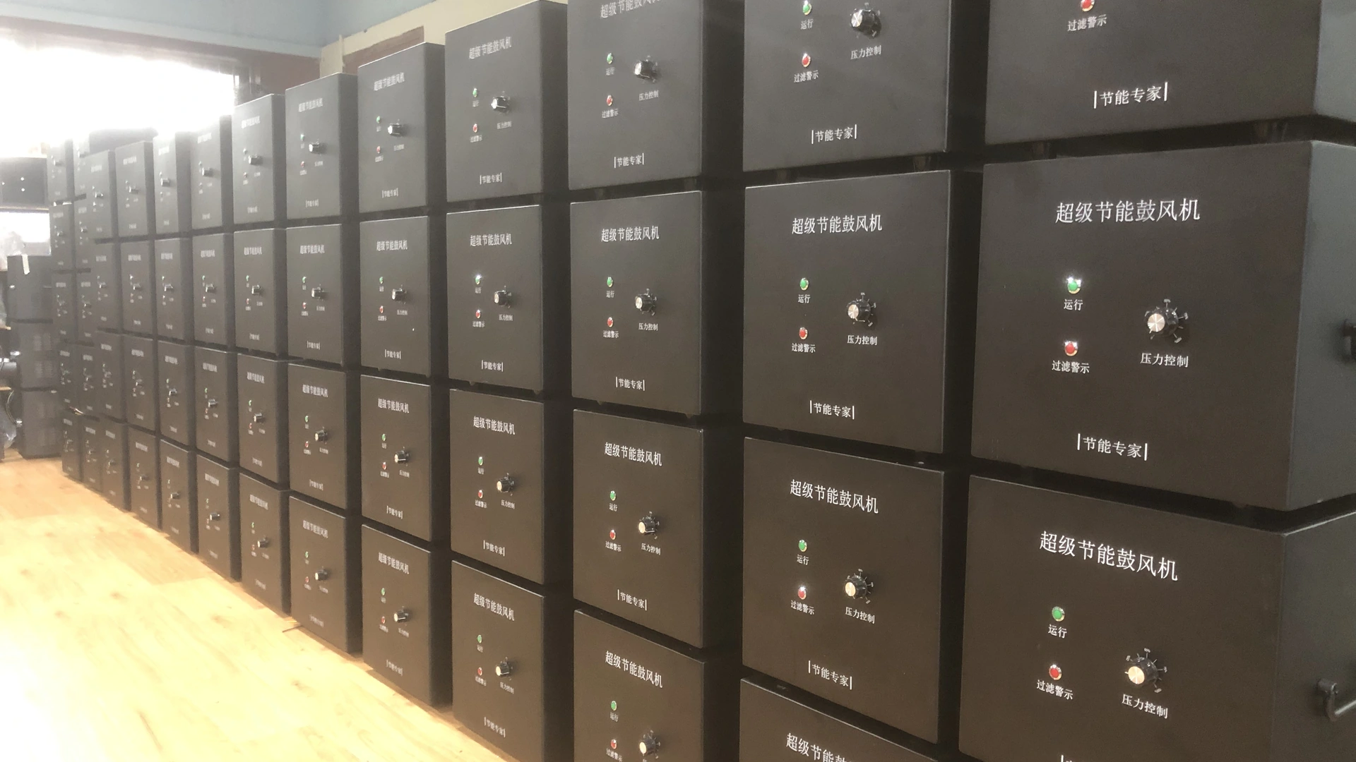
For buyers, the safest approach is to define normal, minimum and peak operating points before comparing brands. Maximum airflow, maximum pressure and motor kilowatts do not describe how a blower will perform at basin depth with real diffuser and piping losses.
Quick Answer
Start with the process designer’s required oxygen transfer and convert it into airflow for the selected diffusers and wastewater conditions. Add hydrostatic pressure from maximum operating depth, diffuser resistance, pipe friction and control losses. Plot every important duty point on the exact blower curve.
Then check turndown, dissolved-oxygen control, redundancy, site environment, electrical supply and maintenance access. Accept a proposal only after the supplier states its assumptions and the system is commissioned against both process performance and measured energy.
Establish the Oxygen Requirement
Wastewater aeration demand varies with influent load, treatment objective, temperature, process configuration and operating strategy. The calculation belongs to the qualified process designer. A blower supplier should not replace it with a generic airflow per tank volume.
Document average and peak oxygen demand, required dissolved-oxygen range and any mixing or minimum-air requirement. Separate design capacity from present loading. A plant may need future peak capacity but operate much of the year at a lower point; that difference drives the control and staging decision.
Where diffuser performance is based on clean-water testing, state the correction approach used for wastewater, depth and site conditions. Keep assumptions visible so the owner can update the calculation when loading changes.
Convert Oxygen Demand into Airflow
Airflow is determined by the oxygen-transfer performance of the complete aeration system. Diffuser type, density, submergence, fouling, basin geometry and wastewater properties influence how much oxygen actually enters the liquid.
Use the diffuser supplier’s applicable data and verify the permissible flow per diffuser. Too little flow can produce uneven distribution or poor mixing; too much can reduce transfer efficiency or exceed component limits. Count the diffusers in each zone and identify which zones run together.
Do not add large unexamined safety factors at every step. Cumulative margins can create an oversized blower that spends most of its life throttled or venting. State one defensible design allowance and retain separate operating points for normal and peak duty.
Calculate Total Discharge Pressure
The blower must overcome four main components:
- hydrostatic pressure at the maximum active water depth;
- diffuser pressure loss at the design flow and condition;
- friction and fitting losses through headers, branches and valves; and
- any required control or measurement-device loss.
Calculate losses at the relevant airflow. Pipe loss rises as velocity increases, so the peak-flow point often needs the closest review. Check the most remote and most restrictive air path, not only the nearest basin.
For an existing plant, record blower discharge pressure, branch pressure, active valves, water level and diffuser condition. A pressure reading without those details cannot be compared reliably. Trending can also reveal fouling: increasing pressure at a similar command and process state often indicates rising resistance.
Use a System Curve and Multiple Duty Points
The installed system has a static pressure component from water depth and a variable loss component that changes with flow. The blower operates where its pressure-flow curve meets this system curve.
Maximum pressure and maximum airflow on a datasheet are separate endpoints; they are not available simultaneously. Ask the supplier to plot minimum, normal and peak points on the curve for the exact model and control setting. Confirm that operation stays within allowed limits.
One large peak point is not enough. Wastewater plants often spend many hours below design load. A model that reaches peak flow but cannot operate efficiently or stably at normal demand may have a poor lifecycle result.
Decide Between Turndown and Staging
Variable output can follow process demand, but each blower has a practical operating range. Below that range, the system may require a minimum command, bypass or different staging arrangement.
Multiple smaller blowers can provide redundancy and broader plant turndown. One unit can serve lower demand while additional units start as load rises. However, headers, check valves and control logic must prevent backflow and unstable sharing.
Define how dissolved-oxygen signals command airflow. Sensor location, cleaning, calibration and response delay matter. Provide minimum aeration and a safe fallback if a sensor or communication signal fails. The control strategy should be commissioned under real load, not accepted from a screen display alone.
Towwind Range: Check the Pressure Boundary First
Request the released exact-model curve and operating limits before considering any Towwind unit. Compare minimum, normal and peak basin duty, including water depth and diffuser loss; if the required duty lies outside verified capability, use another solution.
Confirm the selected model’s control range, electrical supply, environmental rating, certification, noise and dimensions from current released documentation. Adjustable output does not replace a verified pressure-flow match.
Many wastewater basins, especially deeper installations, may require more pressure than a proposed model can provide at the needed flow. Reject any candidate whose verified curve does not cover the duty.
Redundancy and Failure Response
The plant must continue meeting its permit and process requirements during maintenance or a blower fault. Define the required firm capacity with one unit unavailable, rather than treating spare capacity as an optional accessory.
Review duty/standby arrangements, automatic changeover, isolation and check valves, backup power and alarm routing. Test the standby unit under load and rotate equipment if the operating strategy requires it. Confirm that a failed unit cannot become an open backflow path.
Alarm records should distinguish power loss, control fault, protective trip and process low-oxygen conditions. Operators need an action plan, not only a red light.
Installation and Environment
Wastewater sites can expose equipment to humidity, corrosive gases, dust and flooding. Locate the blower in a dry, ventilated area and verify the selected model’s released environmental rating; do not assume immersion or corrosive-atmosphere suitability.
Keep the inlet and cooling path clear. Draw intake air from a location that minimizes corrosive vapor and spray. Support piping independently, provide a suitable flexible connector and follow the engineered design for isolation, check and relief devices.
Verify voltage, phase, frequency, current, cable, grounding and protective devices for the exact model. Confirm compatibility with generators or emergency power where required.
Maintenance and Performance Trending
At commissioning, record a baseline for defined basin and process conditions: airflow, discharge and branch pressure, blower setting, electrical input, dissolved oxygen, water level, active diffusers and ambient condition.
Trend pressure and power with airflow. Rising pressure can point to diffuser fouling or restriction. Falling pressure with reduced process air may indicate leakage. A change in dissolved oxygen at unchanged air delivery can reflect process loading, sensor condition or transfer performance.
Inspect filters, cooling passages, connectors, headers, valves and alarms on a schedule based on the environment, measured condition and final manual.
Verify Energy and Lifecycle Cost
For wastewater aeration, compare measured input only after both options satisfy the required oxygen-transfer duty and basin operating points. Record diffuser condition, control mode, hours and process acceptance before calculating lifecycle energy cost.
Measure complete package power at representative flow and pressure. For staged systems, include each combination and annual hours. Compare energy while maintaining equivalent treatment and dissolved-oxygen requirements.
Annual energy is the sum of measured average input for each mode multiplied by the hours in that mode. Procurement should also compare installation, controls, diffuser maintenance, spares, warranty, service response and the cost of process interruption. A lower purchase price does not offset an unsuitable pressure range or weak support plan.
Information to Send with an RFQ
Provide:
- treatment process and design oxygen basis;
- basin dimensions and minimum/maximum water depth;
- diffuser type, quantity, layout, flow range and expected loss;
- normal, minimum and peak airflow;
- piping, fittings, valves and calculated losses;
- required pressure-flow duty points;
- current blower readings for a retrofit;
- voltage, controls, alarms and communication;
- ambient and corrosive conditions;
- redundancy and backup-power requirement; and
- commissioning and acceptance criteria.
Ask every bidder to return the model curve with the duty points shown, predicted input at each point, assumptions and exclusions. That makes performance and lifecycle comparisons traceable.
Final Recommendation
Wastewater aeration blower selection starts with process oxygen demand and ends with verified operating points, control and redundancy. A low-pressure energy saving blower may suit a shallow or otherwise compatible system, but the calculated depth and losses must fit its curve.
Do not stretch a model beyond its verified range to achieve a lower power rating. A technically honest “not suitable” is better than a low-cost blower that cannot support treatment. When the duty fits, controlled output and measured baselines can help reduce energy without compromising the process.
Frequently Asked Questions
Can wastewater airflow be sized from basin volume?
Not reliably. Oxygen load, wastewater conditions, treatment objective, diffuser performance, depth and mixing requirements all influence airflow.
Why is basin depth critical?
The blower must overcome hydrostatic pressure from submergence before accounting for diffuser and piping losses. Deeper water requires more pressure.
Are Towwind blowers suitable for every aeration basin?
No. Usable airflow at the required basin pressure must be confirmed on the released exact-model curve. Deeper systems may require another technology.
How should aeration energy be compared?
Measure complete blower input at equivalent airflow, pressure and treatment conditions across representative operating modes. Include staging and annual hours.
What data help diagnose diffuser fouling?
Trend airflow, discharge and branch pressure, blower command, power, water level and dissolved oxygen against the commissioning baseline.