
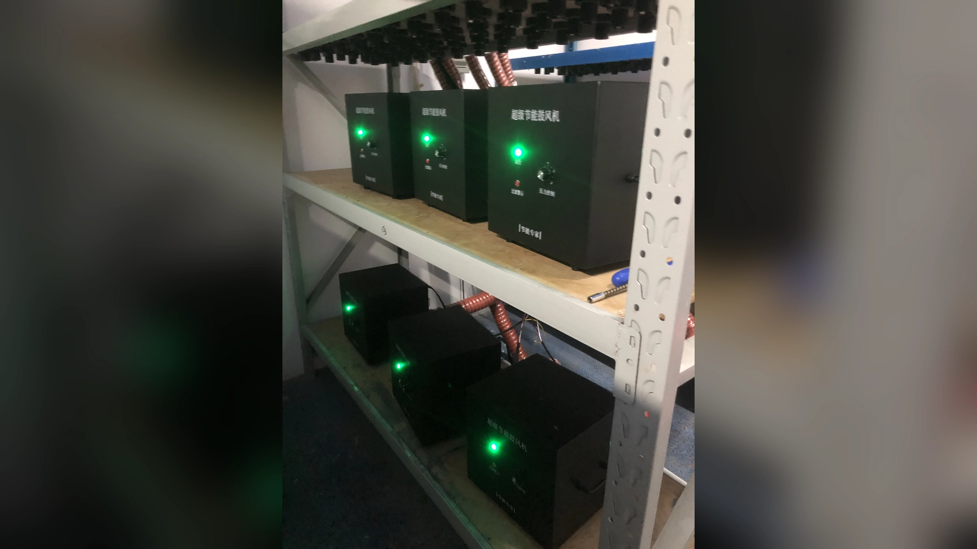
Good control begins with the physical air system. A badly placed sensor, leaking branch, sticky valve or oversized blower cannot be corrected reliably by aggressive software tuning.
Quick Answer
Define safe minimum and maximum speeds from the exact blower curve and process tests. Place the feedback sensor at a representative, stable point. Use reasonable acceleration and deceleration ramps, deadband or filtering, and conservative control gains.
Test branch changes, filter loading, line-speed transitions and every product recipe. Monitor actual speed, airflow, pressure, current, real power and temperature. If the loop hunts, diagnose sensor location, system delay, valve movement and controller tuning before increasing speed or widening limits.
Define What Must Remain Stable
Pressure stability alone may not guarantee process stability. An air knife can show steady plenum pressure while a product still receives uneven coverage. An aeration header can hold pressure while branch flow changes.
Define the acceptance criteria: pressure range, airflow, dryness, cleaning quality, dissolved oxygen response or another process result. Include current and temperature limits.
Specify how quickly the system must recover after a demand change and how much temporary deviation is acceptable.
Establish the Safe Speed Range
Use the exact model’s P-Q curves and manufacturer limits. Mark minimum, normal and peak duties, then verify them through commissioning.
Minimum speed may be governed by motor or controller cooling, stable aerodynamic operation and process requirements. Maximum speed is limited by current, power, temperature, mechanical design and the curve.
A 0-100% command does not prove that the complete range is available for continuous operation.
Choose a Representative Pressure Point
A sensor near the blower outlet responds quickly but may not represent a distant process. A remote sensor represents useful pressure better but introduces pipe delay and can be affected by local branch turbulence.
Avoid pressure taps directly after a sharp elbow, valve or pulsing outlet when a more stable location exists. Keep tubing short, protected and free from water or blockage.
Document the point and units. Moving the sensor after commissioning changes the control system.
Verify the Sensor and Signal
Check sensor range, zero, calibration, engineering-unit scaling and analogue or digital signal. An oversized range can reduce useful resolution; a narrow range can saturate during peak duty.
Compare the controller display with a calibrated reference. Inspect pressure tubing for leaks, kinks and contamination.
Do not tune the loop around a faulty reading. Preserve raw values and alarm history before making changes.
Understand System Delay
Pipe volume, distance, branch valves and terminal response create delay between a speed command and measured pressure. A large header may respond slowly, while a compact air-knife manifold reacts quickly.
If the controller responds again before the system settles, it can overshoot and reverse repeatedly. Measure the step response during a controlled test.
Use that observed delay to choose scan time, filtering, ramp and control gains.
Use Acceleration and Deceleration Ramps
A sudden speed increase can create pressure overshoot, current peaks and abrupt product disturbance. A sudden decrease can drop process pressure before the controller or line reacts.
Set ramps long enough for stable response but short enough for production needs. Acceleration and deceleration may require different values.
Test startup, normal recipe changes, emergency response and restart separately. Do not tune a normal ramp by compromising the emergency-stop function.
Apply Deadband Carefully
Deadband prevents the controller from reacting to every small pressure fluctuation or sensor noise. Too little can cause constant speed movement; too much can allow unacceptable process variation.
Set deadband from actual process tolerance and measurement resolution. Observe the weakest branch or product, not only the sensor display.
Record the final value and reason. An unexplained wide deadband can hide a poor sensor or oversized blower.
Use Signal Filtering Without Hiding Faults
Filtering can smooth turbulence or electrical noise, but excessive filtering delays real changes. The controller may respond after process pressure has already fallen.
Correct sensor location, grounding, shielding and tubing before relying on heavy software filtering. Compare filtered and raw trends during commissioning.
Alarm logic may need a different delay from the control signal so protection remains effective.
Tune Feedback Conservatively
Proportional, integral and derivative settings determine how the controller reacts. Excessive proportional gain can amplify small errors. Too much integral action can build up during saturation and cause overshoot.
Begin with supplier or controls-engineer guidance and a safe test plan. Change one parameter at a time and record the result.
Use anti-windup or output limiting where supported. Never tune beyond current, speed or process limits.
Consider Recipe-Based Control
When demand states are predictable, validated recipes can be simpler and more stable than continuous pressure feedback. A recipe may set speed according to product, conveyor rate and number of active air knives.
Record pressure, airflow, power and accepted result for each recipe. Protect settings from unauthorized adjustment and maintain revision history.
A pressure trim can be added where needed, but complexity should solve a real process problem.
Coordinate Branch Valves and Blower Speed
When a branch opens, system resistance falls and total demand changes. If the blower reacts before the valve reaches position, or both controllers fight each other, pressure can oscillate.
Sequence valve movement and speed commands deliberately. Use valve position feedback when critical. Test the shortest and most restrictive branches.
Correct gross branch imbalance through pipe layout and diameter before tuning the central blower around it.
Prevent One Loop from Fighting Another
A machine may contain a blower pressure loop, branch flow loops and process quality control. If each changes output independently, they can create slow oscillation.
Define which loop has authority and how setpoints are coordinated. Avoid a pressure controller increasing speed while a downstream valve closes to reduce flow.
Trend commands and feedback together so the interaction is visible.
Handle Filter Loading
As an inlet filter loads, pressure loss rises. An automatic controller may raise speed to maintain process pressure, hiding the maintenance problem until no margin remains.
Monitor filter differential pressure and set a maintenance warning. Limit automatic compensation to the approved range.
After filter replacement, the controller may need less speed. Verify current, pressure and process result rather than leaving the higher command in place.
Protect Electrical and Thermal Limits
Monitor phase current where applicable, real input power, motor and controller temperature and ambient conditions. Qualified personnel should verify supply and protection.
Use the installed unit’s nameplate and current model manual for current limits, electrical protection and wiring; do not substitute figures from another model or supply version.
Do not widen a speed limit to prevent a low-pressure alarm. Find the restriction or revise the blower selection.
Applying Towwind Product Data
Confirm the selected model’s current specification, pressure-flow curve, electrical nameplate and installation requirements before assigning an operating point.
The endpoints are separate. Every approved speed recipe must lie on the exact curve at simultaneous pressure and airflow.
Confirm command type, feedback, alarms, ramps, minimum and maximum settings from the final controller documentation.
Test Disturbances, Not Only Steady Operation
A stable normal point does not prove robust control. Test:
- one or more branches opening and closing;
- conveyor acceleration and deceleration;
- product recipe changes;
- clean and normally loaded filter conditions;
- approved idle and restart modes;
- supply interruptions and alarm recovery; and
- the credible peak production demand.
Observe pressure overshoot, recovery time, current, temperature and process quality.
Record High-Resolution Trends
Log setpoint, measured pressure, speed command, actual speed, valve positions, current and alarms at a sampling rate appropriate to the system response.
Slow hourly readings cannot reveal a ten-second oscillation. Conversely, very fast data adds noise and file size without helping a slow header diagnosis.
Mark production events on the trend. This links pressure changes to branches, products and operator actions.
Energy and Stability Must Be Balanced
The lowest speed setting may minimize instantaneous power but create rejects or slow recovery. Excessive pressure margin stabilizes the process but wastes energy.
Find the lowest stable setting that passes the process across expected variation, then add a documented margin. Measure real input and hours by mode.
Stable operation and process acceptance take precedence over an assumed saving. Compare measured input only after settings meet the required duty.
Commissioning Sequence
- Correct leaks, filters, pipe restrictions and branch imbalance.
- Verify sensor location, range, zero and signal scaling.
- Define safe speed, current and pressure limits.
- Establish a stable manual operating point.
- Apply conservative ramps and control gains.
- Test one demand change at a time.
- Validate every recipe and credible branch combination.
- Confirm alarms, limits and fallback behavior.
- Measure energy and process results by mode.
- lock approved parameters and preserve the baseline.
This order prevents software from masking a physical system fault.
What to Provide a Supplier or Controls Engineer
Send the exact blower and controller model, P-Q curves, process pressure and airflow, sensor range and location, pipe volume, branch sequence, valve timing, production recipes, required recovery time, electrical supply and recorded trends.
Include the current limits, alarms, temperature and process acceptance criteria. State which parameters can be changed and who owns approval.
Clear information reduces trial-and-error tuning during production.
Conclusion
Stable blower speed adjustment depends on sound measurement, defined limits and a control response matched to the physical air system. Ramps, deadband, filtering and gains should support the process rather than conceal leaks, restrictions or poor branch design.
Commission every demand transition, not just one steady point. When pressure, speed, current, temperature and product quality are trended together, the blower can follow changing demand without hunting or wasting an excessive stability margin.
Frequently Asked Questions
Why does blower pressure keep oscillating?
Possible causes include excessive controller gain, integral windup, sensor turbulence, system delay, interacting valves, leaks or an oversized blower.
Where should the pressure sensor be installed?
Use a representative stable point agreed during design. Avoid highly turbulent locations and document whether it represents blower outlet, header or process pressure.
Should blower speed change instantly with conveyor speed?
Not necessarily. Coordinated ramps may prevent pressure overshoot or undershoot. Validate response against the actual product and line dynamics.
Can automatic pressure control hide a dirty filter?
Yes. It may raise speed as filter loss grows. Monitor filter differential pressure and limit compensation to the approved range.
What data helps tune a blower loop?
Trend setpoint, pressure, speed command, actual speed, valve positions, current, alarms and process events at a suitable sampling rate.