
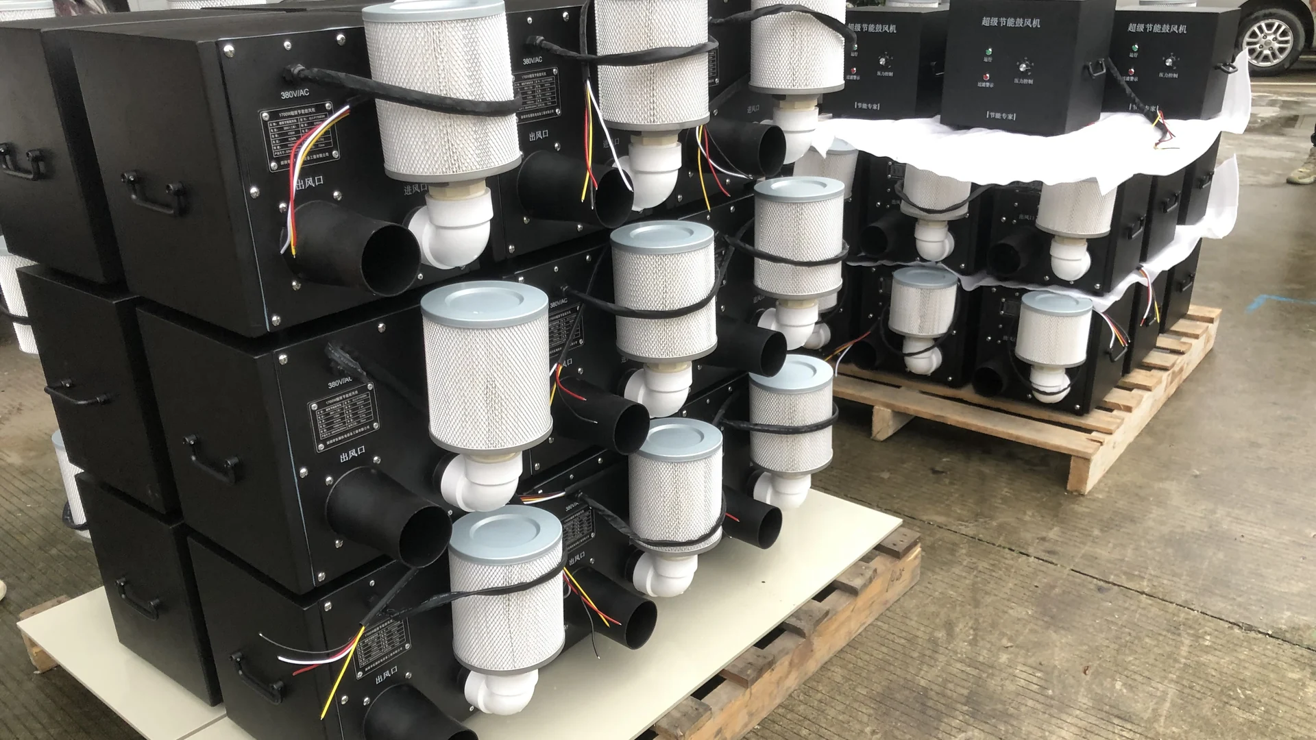
The safest projects begin with a measured baseline and a written method statement. They finish with a loaded process test, energy record, operator handover and rollback decision—not merely a successful start command.
Quick Answer
Document the existing duty and air path, select the new blower at the combined airflow-pressure point, engineer mechanical and electrical interfaces, prepare the work offline, install during a controlled outage and commission against the original process criterion. Keep a rollback plan until acceptance is signed.
Phase 1: Record the Existing System
Photograph the old nameplate, blower orientation, inlet filter, connections, mounting, pipe supports, valves, gauges, cables and control terminals. Mark flow direction and measure connection sizes rather than estimating them from a catalogue photograph.
Record pressure and airflow at identified points under normal and most demanding production modes. Log running current or input power, valve positions, active branches, filter condition, production speed and accepted process result. If airflow is calculated or inferred from velocity, state the method and assumptions.
The old motor rating is supporting information, not the replacement duty. A 3.0 kW ring blower may be oversized, while another unit with the same rating may operate near its curve limit. The baseline separates those cases.
Phase 2: Select the New Blower at the Operating Point
Map losses through the inlet, silencer, pipe, bends, reducers, valves, manifolds and terminal devices. Define minimum, normal and peak modes. The proposed blower must supply the required airflow at the required pressure—not separate catalogue maxima.
TW750B, TW1500B and TW2000B are shortlist family names; their exact released specifications and delivered variants must be confirmed before selection.
Use TW750B, TW1500B and TW2000B as shortlist families, not as evidence of delivered airflow or pressure. Request the released model curve, exact electrical variant and final connection drawing before choosing a retrofit candidate.
Maximum pressure and maximum airflow are separate curve points; do not treat them as simultaneous duties or infer the exact values from conflicting source sheets.
Use the applicable performance curve or verified point data. Check normal operation as well as the limit. A candidate that barely covers peak duty may leave inadequate margin for normal filter loading or product variation.
Phase 3: Freeze the Retrofit Scope
Prepare one scope covering equipment, accessories, installation and commissioning. Identify who supplies:
- the exact blower and electrical variant;
- controller and control cable;
- inlet filter and consumables;
- inlet/outlet adapters and flexible connections;
- isolation or check valves where needed;
- baseplate, fasteners and vibration provisions;
- protective devices, wiring and grounding;
- PLC programming and alarm integration;
- instruments and acceptance test labor.
Unassigned items become outage delays. Review each quotation against the same scope so purchasing does not compare a bare blower with a complete retrofit package.
Phase 4: Engineer the Mechanical Interface
Check the final model drawing, not a family photograph. Confirm dimensions, weight and connection details for the delivered unit before fabricating adapters.
Design reducers and adapters with smooth transitions where practical. Avoid an abrupt small-diameter section that creates avoidable loss. Support external pipework independently; the blower casing should not pull misaligned rigid pipe into position. A suitable flexible connection can accommodate minor movement and simplify removal, but it should not hide poor alignment.
Leave clearance for cooling, filter removal, electrical access and normal service. The specification describes indoor use and warns against blocked inlets, water immersion and condensate backflow. Wet processes need drainage and backflow protection designed into the air path.
In parallel or standby systems, provide isolation so one running blower cannot push through another. Review startup and shutdown sequence before fabrication is frozen.
Phase 5: Engineer Electrical and Control Integration
Confirm whether the selected model is the 220 V single-phase or 380 V three-phase version. Current ratings differ by family and voltage. Protection, cable size, disconnect, grounding and terminal arrangement must follow the exact delivered documentation and local requirements.
Document start/stop command, output command and scaling, run feedback, alarm contacts, reset method, safe state and response after power interruption. Do not assume an old contactor circuit can directly operate an electronic blower package without review.
If the line PLC will select multiple output levels, define each approved production mode and who owns the parameters. Back up final settings. Only authorized personnel should modify protection or internal control values.
Phase 6: Prepare the Outage and Rollback Plan
Fabricate adapters, assemble cables and bench-check controls before the shutdown where practical. Confirm lifting, access, lockout, tools, instruments, parts and responsible personnel. Estimate time for removal, installation, dry checks, loaded testing and correction.
Define rollback criteria. If the new system cannot meet process acceptance within the allowed commissioning window, the team should know whether and how the old blower can be restored. Preserve old fittings and document their condition until final sign-off.
Coordinate the work with production. State the last acceptable restart time, escalation contacts and who can approve an extension. A technically sound retrofit can still fail commercially if an unplanned delay interrupts a critical order.
Phase 7: Install and Perform Cold Checks
After lockout and verification, remove the old blower without transferring unsupported pipe load to nearby equipment. Inspect the exposed air path for debris, liquid and damaged seals. Confirm mounting surface, fastener condition and flow direction before placing the new unit.
Check pipe alignment, flexible connectors, valve positions, filter installation, liquid protection, grounding, insulation, terminal tightness and control wiring. Confirm that the inlet and cooling path remain clear. Do not start against an unintended closed path.
Perform the pre-start checks in the final manual. A brief unloaded or dry check can confirm basic response, but it does not prove production performance.
Phase 8: Commission Under Real Load
Start at a controlled condition and verify command, feedback and alarms. Then operate the complete air path with the real product or process load. Test the most demanding normal mode, not only an easy setup.
Record:
- blower command and feedback;
- pressure and airflow or velocity measurement points;
- electrical input or accumulated energy;
- filter, valve and branch configuration;
- line speed or process load;
- process acceptance result;
- alarms, temperature observations and unusual sound.
Run long enough to reveal heat, changing resistance or unstable distribution. Stop for repeated trips, inadequate output, abnormal current or excessive temperature. Do not raise protection limits to force a pass.
Test lower-demand modes, automatic changes and standby operation where applicable. Approve the minimum setting that reliably meets each process condition rather than leaving every mode at maximum command.
Verify Energy and Complete Handover
Measure old and new systems at the same electrical boundary and equivalent accepted output. Do not calculate savings from the difference between motor ratings.
Saving percentage = (old energy − new energy) ÷ old energy × 100%
Only site data can establish the project’s energy result. Compare measured old and new input at equivalent accepted output, then apply actual operating hours and tariff after the comparison basis is agreed.
Hand over the final manual, drawings, settings, alarm guide, consumable part numbers, maintenance schedule, test readings and sign-off. Set filter inspection and replacement intervals from the delivered manual and site contamination and runtime.
Keep the old and new baselines together. They provide the evidence for energy reporting and help maintenance identify later changes in filter condition, pressure, current or process output.
A Retrofit Is Complete Only After Process Acceptance
Mechanical fit and successful rotation are milestones, not completion. The retrofit is complete when the blower performs every required mode, controls and protection work, measured data is recorded, operators understand the new system and responsible personnel accept the process result.
For a Towwind retrofit review, send the old nameplate, measured duty, air-path drawing, interface photographs, electrical and control details, outage window and acceptance criterion. That package allows risks to be resolved before the line stops.
Frequently Asked Questions
Can a ring blower be replaced without changing the process air requirement?
Yes, when the new blower covers the verified operating point and the existing air path can be connected without reducing process performance. Confirm with a loaded acceptance test.
Should adapters be fabricated before the shutdown?
Where measurements and the final drawing are confirmed, offline fabrication reduces downtime. Keep allowance for verified fit and avoid using adapters to force misaligned pipework.
Can the existing starter be reused?
Do not assume so. Review supply, phase, protection, commands, feedback and alarms for the exact electronic blower package and local electrical requirements.
What should trigger rollback?
Define project-specific criteria such as failure to meet peak process output, unresolved alarms, unsafe integration or inability to complete commissioning within the approved outage.
When can energy savings be accepted?
After old and new energy use is measured at the same boundary while both configurations deliver equivalent accepted process output.