
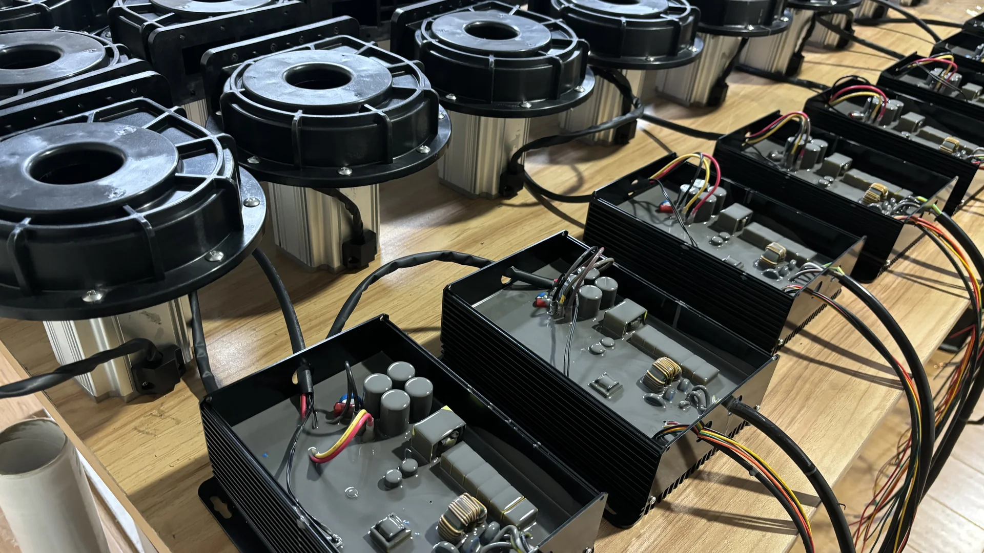
The motor is only the first step. The connected filter, pipework, manifold and outlet create resistance, which determines the blower’s actual airflow and pressure. Real efficiency therefore depends on how the complete package operates on the installed system curve—not simply on the efficiency printed for one component.
Quick Answer: How does an energy saving blower work?
The controller commutates the BLDC motor and regulates its speed. The motor drives the impeller, which adds velocity and pressure to the air. The air system then sets the resistance the blower must overcome. Reducing speed when demand falls can lower electrical input, provided the remaining airflow and pressure still achieve the process result.
The mechanism matters only when it produces the required air in the connected machine. A lower electrical reading is useful evidence after the process result, airflow-pressure duty and test conditions have also been recorded.
From AC Supply to Controlled Motor Speed
The delivered electrical supply feeds the blower’s electronic drive. That drive switches current through the BLDC motor windings in sequence, producing rotation without the brush contact used in a brushed DC motor. Electronic commutation also gives the controller a direct way to manage speed and respond to commands or protection conditions.
Confirm the selected model’s electrical supply, controller interface and usable operating range from its current nameplate and manual; validate each production setting on the installed system.
Changing the command can change air duty, but the usable control range must come from the exact model documentation. Minimum useful output is set by the process; permitted operating limits and cooling are set by the equipment.
How the Impeller Creates Airflow and Pressure
The rotating impeller transfers energy to the air. The casing guides that air toward the outlet, where the connected system resists the flow. With a relatively open air path, the operating point tends toward higher flow and lower pressure. Added restriction moves the operating point toward lower flow and higher pressure.
This interaction explains why blocking an outlet does not create “free pressure.” It changes the load on the blower and may move operation outside a suitable range. Likewise, opening extra branches can reduce pressure available at each terminal even though total flow changes.
Performance must therefore be discussed as an airflow-pressure pair. A pressure reading also needs a location: blower outlet pressure is not automatically the pressure at a remote air knife or submerged diffuser after intervening losses.
What the Towwind Ratings Tell Us About Operation
Confirm the selected model’s current specification, pressure-flow curve, electrical nameplate and installation requirements before assigning an operating point.
For model screening, request the current pressure-flow curve and electrical data for the exact proposed unit; do not combine separate catalogue endpoints into one operating point.
Verify the exact model’s usable control range, electrical supply, protection rating and performance from its current documentation; test the proposed setting against the process requirement.
A difference in rated speed does not allow a buyer to scale airflow or pressure with a simple ratio. Impeller geometry, motor limits and controller programming also matter. Use the applicable curve or verified duty data for an operating-point decision.
Electrical protection and cabling must follow the exact delivered variant’s nameplate and manual. Confirm supply phase, voltage, current and controller connections before integration.
Why Reducing Speed Can Reduce Energy Use
When process demand falls, reducing blower speed can reduce both delivered flow and electrical input. This is fundamentally different from running at full output and wasting excess pressure across a valve. The useful saving depends on where the operating point moves and on the efficiency of the motor, drive and aerodynamic components at that setting.
Do not apply an ideal fan-law calculation blindly to a complete installed package. Fan laws can help engineers understand trends for a geometrically unchanged machine, but controller losses, motor behavior, system characteristics and process thresholds affect measured results. A meter and a process acceptance test settle the question more reliably.
Output control is most valuable when it follows real demand. A drying line may use separate settings for product widths or conveyor speeds. An aeration system may respond to process demand within an approved range. If demand never changes and the unit already operates at the correct duty, controllability alone does not prove a large saving.
Control Signals, Feedback and Alarms
Before integration, the equipment builder should document:
- the required start/stop logic and safe state;
- command signal type and scaling;
- run, fault and speed feedback required by the machine PLC;
- alarm reset behavior and whether fault history is retained;
- interlocks for valves, line operation or standby equipment;
- response after power interruption;
- cable shielding, grounding and separation requirements;
- who owns final parameter settings and backups.
The final delivered manual governs the exact interface. Do not infer terminal functions from another power class or an earlier controller revision. During commissioning, verify the command at several points rather than confirming only that the blower starts.
Cooling and Protection Are Part of the Working Principle
Electrical and aerodynamic losses become heat. The blower must reject that heat through its designed cooling path. Covering the housing, placing the inlet against a panel or recirculating hot exhaust air can undermine otherwise sound operation.
Protection functions may stop the unit when an abnormal condition is detected. A trip is evidence, not an inconvenience to bypass. Maintenance should record the alarm, command, current, pressure, filter condition and recent process changes before resetting when it is safe to do so.
The specification requires a clear inlet, secure grounding, indoor installation and protection against immersion or condensate backflow. These provisions support reliable motor and controller operation; they are not separate from efficiency.
How to Measure Conversion from Electricity to Useful Air
Measure input power at a defined electrical boundary and record the process condition at the same time. Motor nameplate power is a rating, not measured consumption.
Energy Use = Measured Input Power × Operating Hours
For variable operation, measure each meaningful mode and weight it by actual operating hours. Include controller losses consistently if the controller falls within the chosen measurement boundary.
Speed control can reduce input when process demand is lower, but the result depends on the air path, duty profile and existing equipment. Verify any saving at equivalent accepted output.
Pair electrical readings with pressure, airflow or air velocity and the actual production result. Otherwise a lower input reading may simply document reduced air delivery.
Conditions That Change How the Blower Behaves
Filter loading increases inlet restriction and changes the operating point. A partially closed valve, added bend or smaller replacement hose changes the system curve. Parallel blowers can interact if isolation is inadequate, and one unit may influence another during startup or shutdown.
Set filter inspection and service intervals from the selected model manual, measured differential pressure, operating hours and site contamination; do not assume a universal calendar interval.
Only authorized personnel should work on the supply, controller or internal parts. Changing protection settings to keep a restricted or overheated system running hides the cause and can damage the equipment.
A Commissioning Sequence That Shows the Principle in Practice
Begin with rotation, supply and signal checks specified for the delivered unit. Then operate the complete air path with the normal filter, valves, branches and terminal devices in place. An open-outlet run cannot represent the production load.
At minimum, record command, feedback, current or input power, pressure, airflow or velocity measurement location, housing condition, alarms and process result. Repeat at low, normal and demanding production modes where applicable. Run long enough to reveal heat or unstable control.
Keep the accepted readings as a baseline. When a future pressure or airflow complaint appears, the maintenance team can then separate a blower change from a dirty filter, altered valve, leaking pipe or modified control command.
What the Working Principle Means for a Buyer
The BLDC motor and controller make efficient conversion and adjustable output possible. The impeller and casing turn shaft power into air energy. The connected system fixes the operating point, while commissioning proves whether that point meets production demand.
For a Towwind recommendation, send the required airflow and pressure, air-path drawing, operating modes, electrical supply and acceptance criterion. Those facts allow the motor, controller and aerodynamic package to be evaluated as one working system.
Frequently Asked Questions
How does an energy saving blower work?
An electronic controller commutates and regulates the BLDC motor, which drives the impeller. The impeller adds energy to the air, while the connected system determines the final airflow-pressure operating point. Output can be reduced when demand falls, subject to process and equipment limits.
Does lowering blower speed always save the same percentage?
No. The result depends on the system curve, duty change, motor and controller behavior, and required process output. Measure input power at representative settings.
Why can airflow fall when system resistance rises?
The blower moves to a different point on its performance curve as resistance changes. Higher pressure demand generally means a different delivered flow for the same speed.
What is the controller’s role?
It electronically commutates the BLDC motor, regulates speed and manages the defined control and protection functions. Exact signals and behavior must be confirmed from the delivered documentation.
Can the blower be tested with an open outlet?
An open-outlet check may support an initial inspection, but it does not prove production performance. Commission the normal filter, pipework, valves and outlets under a representative process load.
Which commissioning readings should be retained?
Keep the command and feedback, electrical input, pressure, airflow or velocity location, filter and valve state, alarms and accepted process result for each tested mode.