
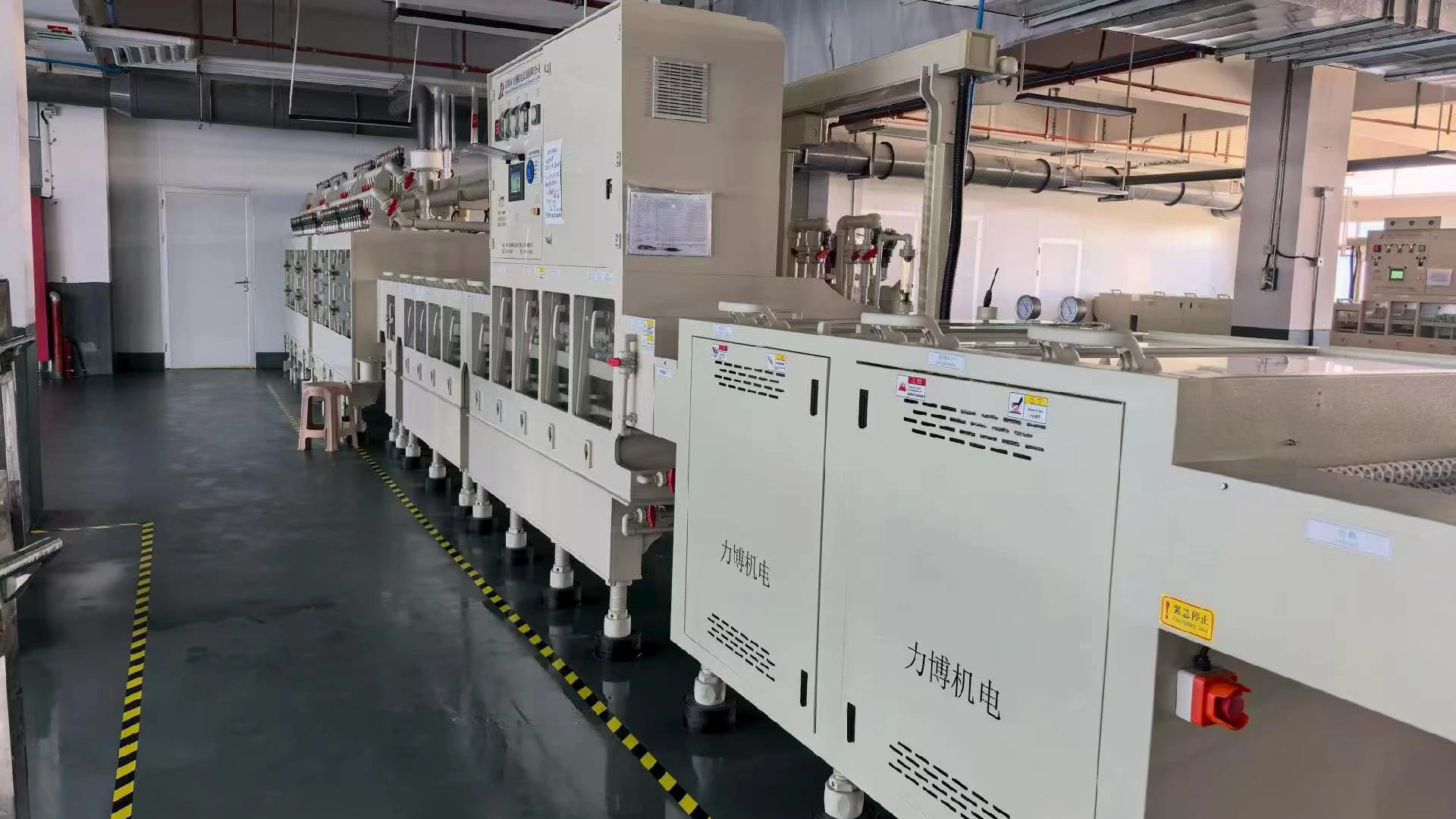
Water trapped in through-holes, conveyor contact areas and recesses can remain even when the upper surface looks dry. The blower, manifold, air-knife angles, drainage and mist extraction therefore have to be assessed as one drying system.
Quick Answer
Choose from the airflow and pressure required by all simultaneous air knives after filter, pipe and manifold losses. Validate with the widest, thinnest and most difficult boards at full production speed, checking both surfaces, holes, edges and conveyor-shadow areas.
Start with the Incoming Board Condition
Document the board range before calculating air demand. Include minimum and maximum width, length and thickness; rigid and flexible constructions; through-hole pattern; surface finish; panel carriers; and any features that can retain water.
Record what enters the drying zone. A board leaving a well-designed final rinse and drainage section carries a different load from one with standing pools. Spray direction, rinse pressure, chemistry, surface tension and the time available for drainage all affect the first air knife’s job.
Do not ask the blower to compensate for avoidable water volume. Improve drainage, roller condition and upstream spray control where practical. Removing a heavy sheet of water efficiently is often easier in stages than trying to evaporate or blast it away at one point.
Divide Drying into Stages
A horizontal line commonly benefits from staged water removal:
- Bulk displacement. The first knives push large water volumes away and support drainage.
- Surface clearing. Following knives remove the remaining film from top and bottom surfaces.
- Detail drying. Final air addresses edges, holes and residual droplets before inspection or the next process.
The exact arrangement depends on the machine. The engineering principle is to give displaced water somewhere to go. If the first knife throws water onto the next drying zone, more blower power may only increase recirculation and mist.
Review Top and Bottom Coverage
Both board surfaces may require drying. Upper knives can reach the visible surface directly, while lower knives must work around conveyor rollers, support rails and drainage paths. Those obstacles create shadows and local pressure loss.
Draw the active knives, slot lengths, angles, standoff distances and branch sizes. Identify which knives operate simultaneously. A manifold that divides air unevenly can leave a distant knife weak even when total blower flow appears adequate.
Knife angle matters. Air should move water toward a controlled drainage direction rather than trapping it at an edge or driving it repeatedly across the board. Adjustable mounts can help commissioning, but final positions should be recorded so operators do not solve one format by upsetting another.
Account for Line Speed and Exposure Time
As conveyor speed rises, each point on the PCB spends less time under the air. The required drying result may therefore need more effective coverage, improved staging or a different air setting. Do not assume blower output scales directly with speed; test the actual product.
Use the highest specified production speed for capacity acceptance. Also test slow conditions where a thin or flexible board may experience the air jet longer and become unstable. If different recipes use different blower commands, protect and document those settings in the control system.
Protect Thin Boards and Small Panels
High local jet force can lift a thin panel, cause flutter, shift a small part or press a board into a roller. The problem is often distribution and nozzle geometry rather than insufficient or excessive total blower capacity.
Test the lightest and narrowest approved board, including leading and trailing edges. Check conveyor grip, opposing top/bottom force and the transition between knife zones. A blower selection that dries the widest rigid board but destabilizes the smallest product is incomplete.
Convert the Air-Knife System into a Duty Point
Determine the airflow required by all active knife slots or nozzles and the pressure needed at their manifolds. Add pressure losses through the inlet filter, silencer, pipe, bends, reducers, valves, branches and fittings.
Pressure must include a measurement location. A reading at the blower outlet is not the same as one at the remote knife manifold. Air velocity at a slot in m/s is not total blower airflow in m³/h unless the effective area and velocity profile are known.
The blower operates where its performance curve meets the connected system curve. Maximum pressure and maximum airflow are separate endpoints; they cannot be combined as one operating point.
Screen the Towwind Range Responsibly
For a proposed model, request the released curve at the combined knife duty and verify the exact electrical, control and installation requirements. Validate the selected setting on wet boards at the required speed and width.
Use the applicable performance curve or verified data for the calculated combined duty. A broad line with several simultaneous knives may need more flow; a restrictive manifold or narrow slot arrangement may demand more pressure. Motor size alone cannot distinguish those needs.
Confirm the selected model’s usable control range, cooling requirement and control interface from its final manual. Validate each board recipe and idle setting in a wet-board trial.
Manage Mist, Heat and the Installation Environment
Displaced water becomes drainage, droplets and mist. Provide a path that prevents mist from recirculating into the blower inlet or settling on downstream equipment. Keep electrical components away from uncontrolled spray and condensation.
Confirm the selected model’s environmental limits in its released manual. Protect the inlet from water immersion and condensate backflow through appropriate drainage, separation and pipe routing, while retaining cooling and filter access.
Warm air may help some drying processes, but this article does not assume a heating requirement. If the line uses heated air, define temperature, materials, safety and energy boundary separately. Do not infer air temperature capability from blower power.
Build a Full-Speed Acceptance Test
Select test boards that cover the real difficulty, not only convenient samples:
- widest board for full knife coverage;
- thinnest or lightest board for stability;
- board with representative holes and recesses;
- maximum normal rinse carryover;
- highest production speed;
- all simultaneous air knives and normal extraction.
Inspect top, bottom, holes, edges and conveyor-shadow areas at a defined point after drying. Record blower command, pressure and airflow or velocity locations, line speed, board type, knife positions, filter and valve state, alarms and result.
Run long enough to reveal mist accumulation, filter changes, temperature rise or unstable distribution. A short dry-board demonstration does not represent continuous wet production.
Measure Energy Only After Drying Performance Is Equal
Measure input power or accumulated kWh at the same electrical boundary for old and proposed systems while both achieve the accepted result at the same line conditions.
Assess energy only after the proposed setup passes the same wet-board acceptance test at comparable board mix and line speed. Compare measured input and operating hours for the complete air system; no general savings percentage predicts a PCB line’s result.
Use separate readings for full production, reduced-width recipes and idle time where commands differ. A controllable blower may reduce output during gaps, but interlocks must ensure it returns to the approved setting before wet boards enter.
What to Send for a PCB Blower Recommendation
Send board range, maximum line speed, incoming water condition, knife drawing, slot dimensions, simultaneous branches, required pressure or airflow, pipe layout, electrical supply, control signals, operating hours and drying acceptance criterion. Add photographs and readings from the existing system for a retrofit.
Towwind can then screen a model against the complete drying duty. The right selection is not the blower with the largest catalogue number; it is the smallest verified package that dries every approved board reliably, integrates safely and leaves a defensible operating margin.
Frequently Asked Questions
What blower is best for a horizontal PCB drying line?
The best blower covers the combined airflow-pressure duty of all simultaneous knives and passes full-speed drying and board-stability tests across the approved board range.
Should PCB drying be sized from total airflow or pressure?
Both are required at one operating point. Airflow feeds active knife area, while pressure overcomes filter, pipe, manifold and nozzle losses.
Why can a board remain wet when outlet pressure looks adequate?
Air may be distributed unevenly or miss holes, edges, lower surfaces and conveyor-shadow areas. Check manifold balance, knife geometry, drainage and measurement location.
Can one blower setting cover every PCB format?
Sometimes, but different widths and speeds may benefit from validated recipes. Every setting must maintain drying quality and board stability.
How should energy savings be verified on a PCB line?
Compare measured kW or kWh while both systems dry the same representative boards at the same line speed and acceptance standard.