
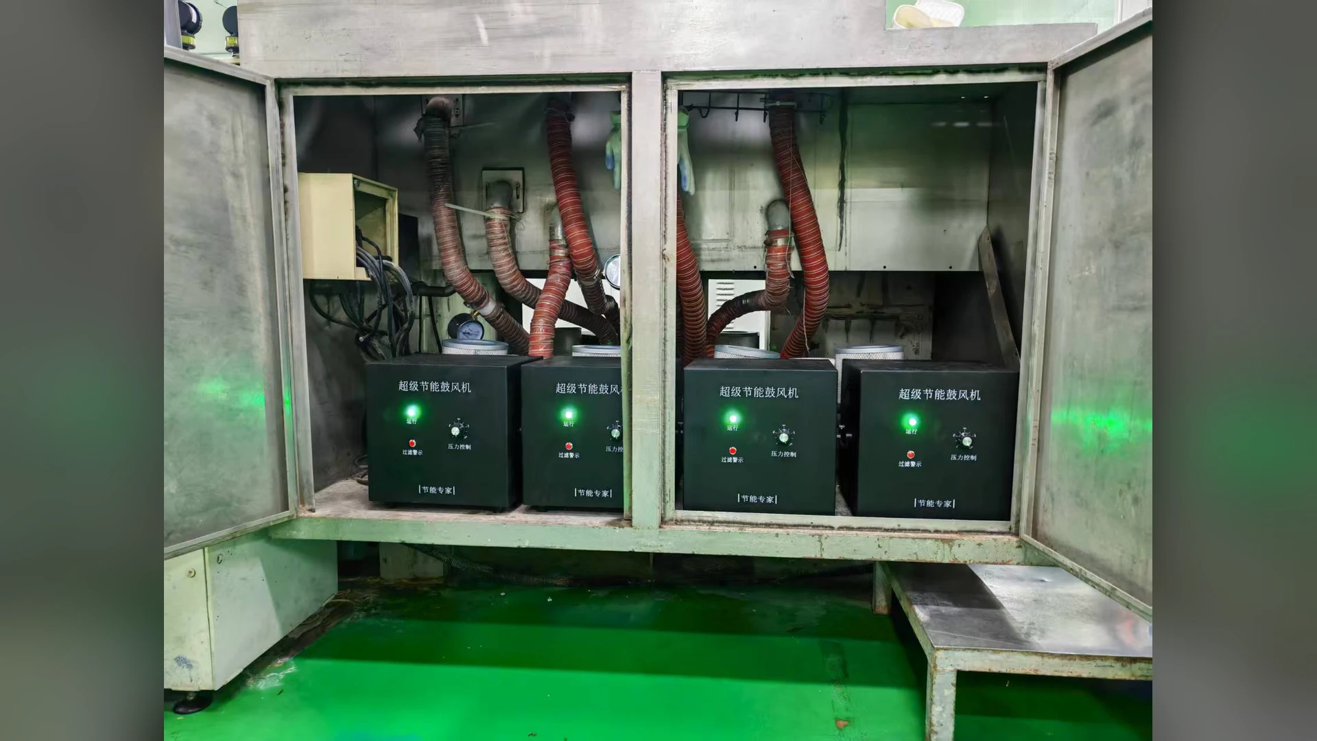
A trip at the moment several air knives start can come from the electrical start sequence, a controller setting, a sudden change in air-system demand or a separate interlock. The fault code and exact event timing determine which path to investigate. Do not assume that every simultaneous-start trip means the blower is too small.
First preserve the controller’s alarm history, the machine state and which knife branches opened. Follow the equipment maker’s isolation procedure before touching wiring or moving parts. The blower alarm evidence guide describes what to capture before a reset.
Build a timeline rather than a single reading
Record the command to start the blower, the blower-ready signal, branch-valve commands and feedback, speed reference, inlet or manifold pressure, current and trip timestamp. A fault before the blower reaches its permitted operating state points toward a different cause from a fault that appears only after multiple valves open. Check whether the machine unintentionally commands the blower to restart for each knife, rather than running one approved sequence.
Read the exact trip category from the installed controller. An undervoltage, overcurrent, overtemperature, communication or external-interlock event should not be collapsed into the same diagnosis. Electrical measurement and controller parameter review belong to qualified personnel using the exact model documentation.
Test the combined air demand
Several knives starting together may move the common header to a new operating point. Record which branches are actually open in each mode, then compare measured or calculated total airflow and the pressure loss through the common path and the most demanding branch. The multi-knife sizing method explains why branch flows add while branch pressures do not simply add.
Check for a valve that opens too quickly, a blocked branch, an unintended bypass closure or a control loop that overcorrects as demand changes. Compare one branch, then the approved simultaneous combination under controlled test conditions. Change one variable at a time and retain the fault log. Do not defeat protective trips to complete a trial.
Check supply and control limits against the actual variant
Confirm voltage, phase, frequency, conductor and protection details against the installed blower and drive requirements. If a speed controller is used, verify acceleration, permitted speed and protection settings with the supplier. A controller parameter copied from another blower may be unsuitable. Towwind’s intermittent-duty guide addresses cycle frequency; this article concerns a particular start event with several air demands arriving together.
If the measured combined duty exceeds the existing blower’s verified curve, compare a suitable configuration of TW750, TW1500 or TW2000 only after documenting the required flow and pressure. A higher nominal wattage is not a substitute for fault diagnosis.
For support, send Towwind the exact alarm, event timeline, electrical supply, valve sequence and simultaneous duty.