
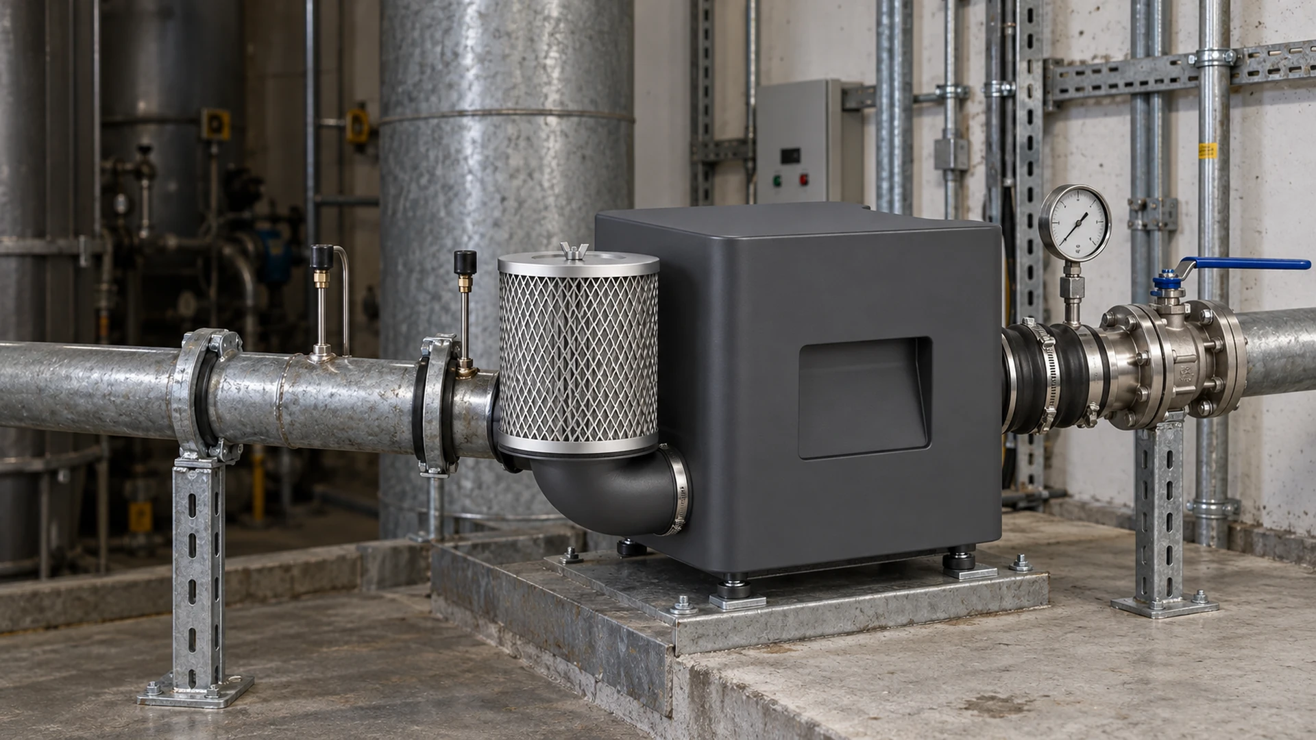
A blower package may arrive with a filter and a pressure gauge already fitted. Once it is connected to a machine, however, that gauge may tell the operator little about the air reaching the process. A restriction between the blower and the final manifold can leave the outlet reading looking normal while an air knife or aeration branch runs short of air.
Where should filters, valves and pressure measurement points go? Start with the complete air path and the question each component must answer. Put filtration where it protects the equipment or process without creating unexamined restriction. Locate valves according to their isolation or control purpose and the selected blower’s safe operating limits. Place pressure taps on both sides of the losses you need to distinguish, using accessible locations suitable for reliable measurement.
There is no universal piping sketch for every blower. Pressure and vacuum systems, open air knives, branched manifolds and packaged machines need different arrangements. The final model manual and the system designer’s safety review govern exact component requirements. This article gives buyers and equipment builders a way to challenge a layout before it becomes difficult to change.
Draw the real air path before choosing tap locations
Trace the route from the air source to the point of use. Include the inlet hood or duct, filter, blower, silencer, flexible connector, valves, reducer, main pipe, branches, manifold and nozzles or diffusers. For vacuum duty, trace the suction path and discharge as well. Mark parts that may clog, move, leak or be shut during operation.
Now define the process requirement. Is the buyer trying to protect a blower from inlet dust, prove manifold pressure at full line speed, watch filter loading or isolate one branch for maintenance? Different questions need readings at different locations. A single outlet gauge should not be expected to answer them all.
On the drawing, identify the pressure basis and location for each proposed value. “Pressure: 20 kPa,” for example, is incomplete without saying whether it refers to blower discharge, a manifold or a remote branch, and under which operating condition it was taken. A measured pressure at one point is not automatically the pressure available elsewhere after filters, valves and pipe losses.
Put the inlet filter where it protects without becoming invisible
An inlet filter is commonly used where incoming air could carry contaminants that harm the blower or process. The required filter type, rating and installation position depend on the selected model, air source and application. Do not assume an inlet filter is always identical across pressure and vacuum configurations, or that an oil-free air source eliminates the need to assess contamination from the surrounding system.
The filter should draw from an acceptable location and be serviceable. An intake beside warm exhaust, washdown spray or a dusty discharge may undermine a good filter specification. A filter hidden above a machine, behind a fixed guard or in a space too small to remove the element will be difficult to maintain. The package designer should show how the element is inspected and changed without loading the blower connection with the filter’s weight.
Also account for the filter’s clean and dirty pressure loss in blower selection. A filter can be clean during factory acceptance and restrictive after months of service. If the process needs a minimum pressure at the last nozzle, the design should not rely on an unrealistically clean filter forever. Use the supplier’s actual filter data and maintenance limit rather than a guessed allowance.
Measure filter condition across the filter
If the purpose is to detect filter loading, measure the pressure difference across the filter or use a model-appropriate restriction indicator. A pressure reading only downstream of the filter may change for many reasons, including a valve position or changing process demand. Comparing points before and after the filter makes the filter’s contribution more visible when readings are taken in a consistent operating mode.
Tap placement and instrument selection still matter. The ports must be suited to the filter housing and the expected pressure or vacuum; they should be protected from blockage and accessible for service. The measurement range and replacement threshold should come from the selected filter or blower documentation. An arbitrary “change at this pressure” number could be wrong for a different filter or duty point.
Record the clean baseline at commissioning. Without it, maintenance has less context for a later increase in differential pressure. If the filter is replaced and the reading remains high, investigate the tap, tubing, housing or other restrictions rather than assuming the new element is defective.
Give every valve a defined job
“Install a valve” is not enough detail for a purchase specification. One valve may isolate a branch for maintenance. Another may control process demand. A check valve, if required, has a different purpose again. A protective device is not interchangeable with any of these. The selected blower type and system configuration determine which devices are necessary and where they belong.
An isolation valve must be placed where the intended section can actually be isolated safely and serviced. Its position should be visible or otherwise verifiable. If a valve can close while the blower is running, the designer must review the effect on the blower and any required protective arrangement. Do not assume every energy-saving blower tolerates a closed outlet or inlet; model-specific operating limits must govern. The same caution applies to a control valve that may be throttled during normal production.
Valves also add resistance and can affect pressure readings. A gauge upstream of a partly closed valve may show healthy blower discharge pressure while the process downstream receives less air. For a critical branch, a second measurement point after the valve can make the difference visible. This is often more useful than adding another gauge beside the first one.
Where a system needs overpressure, backflow or other protection, obtain the arrangement from the appropriate design authority and delivered-model documentation. The requirements vary too much by blower technology and application to prescribe a universal valve sequence in a blog article. Never place an unreviewed isolation device where it can defeat an intended protective path.
Put pressure measurements where decisions are made
A well-chosen set of pressure points separates blower performance from air-path loss. For many systems, the following questions guide the design:
| Decision | Candidate measurement location |
|---|---|
| Is the inlet filter loading? | Suitable points on both sides of the filter, or the package’s specified restriction indicator |
| What is the blower producing? | An approved discharge or suction measurement point identified in the final layout |
| Is the main pipe or valve losing too much pressure? | A point downstream of the component under review, compared with an upstream point |
| Is the process getting what it needs? | A representative manifold or point-of-use location, where measurement is practical |
These are design questions, not a claim that every machine requires four permanent gauges. A small OEM machine may use temporary test ports at commissioning and a single permanent process sensor. A larger branched system may justify permanent points on critical branches. The investment should follow the cost of uncertainty: a lost drying step or an aeration failure can cost more than accessible measurement fittings.
For each point, note whether it reads gauge, differential or another defined pressure basis. Label it on the machine and in the as-built drawing. State the normal operating mode for comparison. A pressure trend is meaningful only when the valve positions, blower setting and process load are reasonably comparable.
Avoid a convenient but misleading tap
Pressure near an elbow, abrupt transition, valve or turbulent discharge may not represent the condition the buyer thinks it does. Measurement geometry and method should be selected by an engineer familiar with the system and relevant guidance. Do not copy a laboratory straight-run dimension into a compact machine without checking whether that method applies.
Keep taps accessible, protect them against contamination and make their reference condition clear. A test point behind a hot pipe or fixed panel is unlikely to be used regularly. A port that fills with condensate or debris can produce bad readings. If the process cannot safely accommodate a tap at the ideal location, agree on a practical alternative and document what it can—and cannot—prove.
For an air-knife line, a manifold reading can help verify the supply near the knives, but it does not by itself prove the product is dry. For aeration, a header pressure reading does not establish distribution across every diffuser. Keep the process acceptance test alongside the pressure measurements. A gauge is evidence about one part of the system, not a substitute for the result the customer buys.
What an equipment buyer should request on the drawing
Before approving a new machine or retrofit, ask for one annotated air-path drawing. It should show filter and valve models, their purpose and normal position, pressure-tap locations, units and measurement basis, and which readings will be captured during acceptance. Include the access needed to change the filter and reach each instrument safely.
Request a short commissioning record made with the complete system assembled: clean-filter condition, valve positions, blower setting, electrical input boundary, pressure readings and process result. The same record becomes a baseline for maintenance. If a future operator sees high blower discharge pressure but low manifold pressure, the team has a route for investigating the path between those two locations.
Purchasing should also clarify scope. An offer that includes a blower and inlet filter but leaves gauges, taps, valve selection or installation to the OEM is not equivalent to a complete instrumented package. The difference affects both installed cost and the ability to verify performance.
Applying the layout to a Towwind proposal
A Towwind Energy Saving Blower may be considered for suitable industrial air-supply duties, including some replacements for traditional ring or side-channel blowers. The selected model still has to meet the required airflow and pressure at the actual system resistance. Filters, valves and the final piping layout can change that resistance, so their positions and losses belong in the selection review.
When requesting a Towwind recommendation, send the full air-path sketch and mark the required process measurement point. Identify the proposed filter, valve modes, branch arrangement, operating schedule and any existing readings with their locations. Ask which measurements the model documentation recommends and which operating limits govern restriction, throttling or isolation. Do not infer those limits from a different blower design.
An energy-saving comparison should use equivalent process output and the electrical input of complete systems under comparable conditions. A different filter, valve position or leaking branch can change the measured result. The product name alone does not establish a savings percentage.
Make the readings useful after handover
Filters, valves and gauges are most valuable when their roles are clear to the next person who services the machine. Put them where they can perform their intended job, label what each reading represents, and keep the baseline with the final drawing. If the layout does not let a technician distinguish a dirty filter from a closed valve or a remote process restriction, revise it before the machine is shipped.
That design discipline makes it easier to verify a new blower proposal, accept the installed system and troubleshoot later changes without guessing from a single number on the outlet gauge.
Frequently Asked Questions
Where should a blower inlet filter be placed?
Place the selected filter in the air path specified for the delivered blower and application, where it draws suitable air and can be serviced. Check its clean and dirty pressure loss in the blower selection. The exact arrangement must follow the model and filter documentation.
Is one gauge at the blower outlet enough?
Not if the decision depends on pressure at a remote manifold or after a valve. The outlet reading does not include all downstream losses. Add appropriately located process or diagnostic points where they will answer a real operating question.
How do you monitor filter loading?
Use the specified restriction indicator or a suitable differential-pressure measurement across the filter. Record a clean baseline in a known operating mode and use the selected filter’s maintenance guidance for action limits.
Can an isolation valve be placed anywhere in the blower pipe?
No. Its position must achieve the intended isolation without exposing the selected blower or system to an unsafe operating state or defeating protection. The correct arrangement depends on blower type, application and the final design.
Do pressure readings prove the process is receiving enough air?
Not by themselves. Pressure at a defined location helps diagnose the air path, but airflow distribution and the actual process result may require separate checks. Compare readings at the documented operating mode and acceptance condition.