
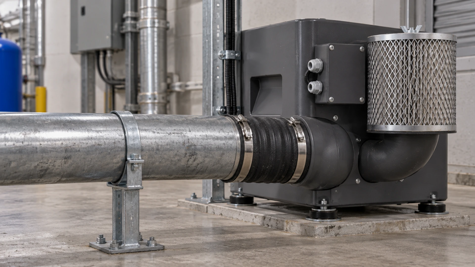
The new blower bolts to its base without trouble. Then the installer brings over the existing pipe, pulls it into line with the blower outlet and tightens the flange. The connection is airtight, but the pipe is now pushing sideways on the blower. A flexible sleeve added afterward may hide the misalignment without removing the load that caused it.
What should a buyer check? The pipe must have its own support and meet the blower without being pulled into place by bolts. Any flexible connector must suit the pressure or vacuum, temperature, movement and air stream, and must not kink, sag or restrict flow. Verify the finished installation at the required process duty.
That is why blower pipe strain and flexible connections deserve their own installation review. The issue is not simply whether the ports match. The blower, its mounting and the connected air system need to remain mechanically compatible when the machine is cold, running and being serviced. A buyer should be able to ask for evidence of that condition rather than accept “the pipe fits” as the whole answer.
Flexible connections can help isolate vibration and accommodate limited movement when designed and installed for the particular duty. They cannot carry an unsupported pipe run, correct a major layout error or make an undersized air path perform like a properly designed one. Exact connector selection and permitted loads must follow the blower and connector manufacturers’ documentation.
What pipe strain looks like on a real machine
Pipe strain is a load transferred from the piping or ductwork into the blower connection. It can arise from misaligned flanges, unsupported pipe weight, a bracket fixed in the wrong position, thermal movement or a rigid connection between parts mounted on different foundations. A small machine can have the same basic problem as a large blower room: the housing becomes an unintended pipe support.
Look for clues before power is applied. Does the pipe spring away when disconnected? Must a technician lever it toward the blower to fit bolts? Is the connector visibly twisted or compressed on one side? Do the fasteners pull the joint into alignment as they tighten? These observations justify stopping the installation and checking supports. They do not, by themselves, identify a failed blower.
During operation, pipe loading may contribute to vibration, noise, loose fasteners, leakage or difficulty removing the blower later. Those symptoms have other possible causes too, so a maintenance team should avoid diagnosing solely from sound. The most useful evidence is the as-installed geometry and what changes when the pipe is safely disconnected under an approved procedure.
Support the pipework independently
The first mechanical question is who carries the pipe’s weight. Hangers, brackets or a frame should support the connected air path according to the system design. The blower connection should not become the convenient last support simply because it is close to the process. This also applies to heavy filters, silencers, valves and manifolds attached near the blower.
Support placement needs some thought. A bracket fixed too far away can leave a short heavy section cantilevered from the blower port. A bracket fixed without allowing for expected movement can transfer thermal growth or machine vibration back into the unit. If the blower sits on vibration isolators while the duct is rigidly tied to the building, the connection must account for that relative movement. The design should be reviewed for the actual mounting arrangement, not copied from a different machine.
For an OEM, place pipe supports on the drawing before the machine frame is fabricated. For a retrofit, inspect the existing supports rather than assuming they remain suitable when a new blower changes port height or orientation. A reducer or adapter can solve a dimensional mismatch yet introduce a new lever arm or concentrated load if left hanging from the unit.
Align the connections before tightening them
Good alignment is visible before the joint is forced together. The blower should be installed in its intended position, the pipework supported, and the mating connection presented without using fasteners to drag the two parts into place. The specific alignment tolerance, flange arrangement, gasket and torque requirements belong to the final product documentation.
An installer should also check what happens when access panels are removed or guards are closed. A hose can be pushed against a sharp edge late in assembly; a manifold can shift when its last bracket is fixed. The final condition matters more than a photograph taken halfway through the build.
If substantial force is needed to make a connection, revise the support or pipe section. Do not count on a flexible connector to absorb a permanent geometry error outside its design range. That approach often leaves the sleeve twisted, under tension or too close to another component. It can also complicate replacement, because the pipe immediately moves when the old blower is disconnected.
What a flexible connector can do
A correctly selected flexible connector may reduce vibration transfer between the blower and pipework. It may also allow limited relative movement where a blower is isolated from its support structure or where expansion is anticipated. The benefit depends on the actual connection design, operating pressure or vacuum, temperature, air-stream contents and movement range.
It is not automatically the best solution for every compact blower. A rigid connection may be appropriate in a machine designed for it, provided loads and vibration are within the manufacturer’s limits. Conversely, adding an arbitrary length of soft hose can introduce pressure loss, leakage risk and unstable geometry. Ask the blower supplier or machine designer whether a flexible connection is specified or recommended for the selected model and mounting arrangement.
The connector’s construction matters. Material compatibility with the air stream, temperature, pressure direction and environmental exposure must be confirmed. A sleeve suitable for a positive-pressure outlet may need different consideration on a suction side, where collapse or inward draw is possible. Some designs require reinforcement or particular installation tension. Use the connector manufacturer’s instructions rather than a generic rule of thumb.
What a flexible connector cannot do
A sleeve is not a structural support. If the adjacent pipe is free to sag, the connector will sag or pull on the blower. It is also not a guaranteed cure for vibration. If vibration comes from the blower’s operating condition, mounting, damaged component or a resonant frame, the source still needs investigation. Isolation may reduce transmission without resolving the cause.
Nor is flexibility an excuse to create a poor air path. A connector pulled too tight, left excessively slack, kinked or squeezed by a nearby guard can change the flow passage. On the suction side, a loose unsupported sleeve may be drawn inward in some designs. Leakage or added resistance can move the blower away from the intended operating point even while the mechanical connection appears convenient.
This is the point where procurement and engineering need the same drawing. A low-cost adapter and sleeve may look cheaper than rebuilding a short pipe run, but the comparison should include supports, replacement access, expected pressure loss and commissioning work. A complete installed scope is easier to price and accept than a list of parts with unresolved geometry.
Inspect the joint at rest and under operating conditions
Mechanical acceptance should start with the blower isolated and the system safe to inspect. Record the support arrangement, connection alignment, sleeve condition and access for later replacement. The inspection must be performed by personnel authorized for the equipment, following the final manual and site isolation procedure; this article is not a live-adjustment instruction.
Then check the finished system during a controlled run at a representative duty point. Look for unusual movement, contact with nearby parts, leakage, changing noise or abnormal vibration. Compare relevant pressure and process readings with the selection basis. A joint that stays mechanically stable but adds enough restriction to reduce process air is not an acceptable installation.
For systems with multiple modes, observe the demanding normal conditions. A variable-speed blower may behave differently across its operating range, and a machine may move between idle and full process duty. If the connected pipework heats or cools during the cycle, inspect for movement after the representative run using an approved safe method.
| Acceptance question | Evidence worth keeping |
|---|---|
| Is the pipe supported independently? | Support locations and photos of the final arrangement |
| Was the connection aligned without force? | Installer sign-off against the final drawing or approved deviation |
| Is the flexible element suitable? | Connector model, duty rating and installation instruction reference |
| Does the air path still perform? | Pressure, flow where measurable, and process result at the tested mode |
| Can the blower be serviced? | Safe disconnection and removal path documented at handover |
An installation issue is not an energy-saving result
Poor pipework can waste energy by increasing system resistance or creating leakage, but there is no defensible universal percentage to assign to a misaligned joint. Likewise, a flexible connector does not by itself make a blower more efficient. If a retrofit is being justified by electricity savings, compare electrical input at the same accepted process output after both the blower and air path are properly installed.
This matters when evaluating a Towwind Energy Saving Blower against a traditional ring or side-channel unit. The proposed Towwind model must meet the required airflow and pressure at the installed system resistance. If a retrofit also changes pipe length, supports, adapters or leaks, the comparison should identify those changes. Otherwise a measured difference in power or process performance cannot be attributed to the blower alone.
Towwind may be a suitable option for some industrial air duties, but fit depends on the selected model, mounting, air path and operating schedule. Share the existing blower details, process requirement and photographs or drawings of the connection area. Ask for the model-specific port arrangement, any permitted loads or connector guidance, and what should be checked during installation and commissioning. Do not assume the new unit has the same port height or support capacity as the old one.
What the buyer should put on the purchase review
Before approving an installation quote, ask who supplies pipe supports, adapters and any flexible connector; who checks fit at the machine; and who owns changes if the delivered port position differs from the drawing. Make independent pipe support, unforced alignment and the required process result explicit acceptance points. If the installer proposes a flexible connector to resolve a mismatch, request its model and rated duty before approving the substitution.
Also ask for an as-built record. It need not be elaborate: a marked drawing, component list, installation photos and commissioning readings may be enough. What matters is that maintenance can later tell whether a sagging hose, missing bracket or changed filter arrangement is a new condition rather than part of the original design.
The best time to solve pipe strain is before the joint is tightened. With support, alignment and connector selection agreed early, the blower can be installed without using its housing to correct the pipework. That is a better basis for stable operation—and for a fair assessment of any energy-saving replacement.
Frequently Asked Questions
What is pipe strain in a blower installation?
It is mechanical load imposed on the blower connection by attached pipework or ducting. Common sources include unsupported weight, misaligned connections, rigid links between differently mounted structures and thermal movement. The exact allowable load is model-specific.
Does every blower need a flexible connector?
No. The need depends on the blower, its mounting and the system design. Flexible connectors are often useful for vibration isolation or limited relative movement, but they must be specified for the application and installed correctly.
Can a flexible sleeve correct a misaligned pipe?
It may accommodate limited designed movement, but it should not be used to hide a major alignment error or support pipe weight. Correct the pipe supports and geometry first, then use a connector within its rated range if the design requires one.
Can a poor flexible connection reduce airflow?
Yes. A kinked, collapsed, leaking or excessively restrictive connector may add system loss or reduce the available passage. Verify the finished system’s pressure and process result, not merely that the sleeve is attached.
What should purchasers request from an installer?
Ask for the support and connector scope, model-specific installation basis, evidence of unforced alignment and a commissioning record at the required duty. Keep an as-built drawing or photographs for future maintenance.