
An enquiry that says “we need a 4 kW blower” tells a supplier very little about the air the process needs. Even “high airflow and high pressure” is too vague to select a machine. The useful specification is a blower operating point: the required airflow at the pressure or vacuum the system imposes while the process is running.
This distinction matters to buyers. Two blowers with the same motor rating can deliver different flow at the same pressure. A catalogue may show an attractive maximum airflow and an attractive maximum pressure, but those values usually occur at different points on its curve. Ordering from the two maxima can leave a machine short of air on site—or paying for capacity it never uses.
Defining the duty point first makes the quotation easier to check. It also gives maintenance and production teams a fair basis for testing a replacement blower after installation.
What Is a Blower Operating Point?
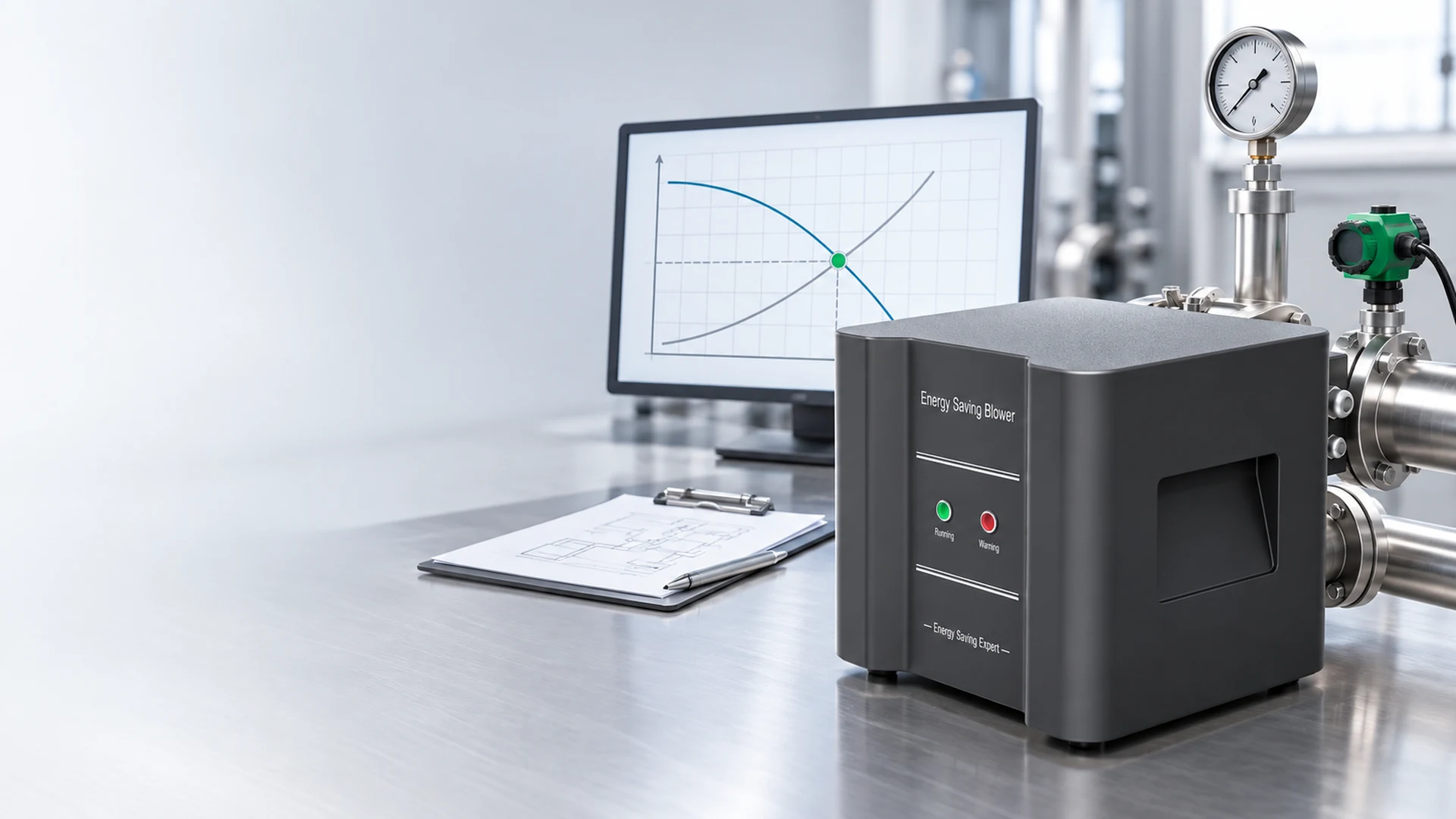
The operating point is the airflow a blower delivers against the resistance of the connected system at a particular speed and set of conditions. On a performance chart, it lies where the blower curve and system resistance curve meet.
In practical purchasing terms, write it as required airflow at required pressure or vacuum, with the units, measurement location, and operating condition stated. For example, a process pressure reading without the corresponding flow is only half a specification. Likewise, free-air flow does not establish delivery through filters, pipework, and nozzles.
If the process has several modes, it may have several operating points. A normal production point, a reduced-load point, and a credible peak condition are more useful than one unexplained “worst-case” number.
Begin with the Process Result
Do not start with a blower catalogue. Start with what the air must accomplish.
For an air-knife line, the outcome may be a defined drying result at a specified conveyor speed and product width. For a vacuum fixture, it may be a holding level while expected leakage is present. For aeration, it may be the air delivery needed at the diffuser under the normal liquid level. These applications do not share one universal flow or pressure target.
Record the process condition alongside the air requirement:
- Product, machine, and operating mode
- Production speed or throughput
- Number of stations operating together
- Required quality or process result
- Normal and peak demand
- Known leakage, filter loading, or seasonal variation
If the process has never had a measured airflow target, note that gap. A supplier can help develop a test plan, but a precise-looking estimate should not be presented as measured fact.
Determine the Airflow Needed at the Process
Airflow should be specified where it is useful, not merely at the blower outlet. In a branched system, one total flow value can hide an under-supplied branch. Record the needs of critical stations and whether they run at the same time.
On existing equipment, a suitable flow instrument may allow direct measurement. The method depends on pipe geometry and access; poor measurement locations can distort readings. When direct measurement is not practical, the existing blower model, its performance curve, measured pressure, speed, and valve positions may support an estimate. Label that estimate clearly.
Check the flow basis and units. A supplier may quote actual volume at the inlet or a standardized volume. Air temperature, pressure, and altitude affect density, so figures stated on different bases should not be treated as equal without conversion.
Do not simply copy the old blower’s catalogue maximum. The installed blower may be oversized, restricted, leaking, or operating far from that maximum.
Measure Pressure or Vacuum at a Meaningful Location
Pressure is meaningful only when its location is known. A gauge at the blower discharge includes losses between the blower and process. A reading at the air knife or manifold may be lower. On a vacuum system, the pressure at the suction tool can differ from the blower inlet.
State whether the reading is gauge pressure, absolute pressure, or vacuum, and include the unit. Also record whether it was taken during normal production, peak demand, or with the line disconnected. An open-pipe reading will not represent normal system resistance.
For an existing installation, readings at two or more locations can help identify where pressure is being lost. A high discharge pressure paired with inadequate air at the process can point to a restrictive filter, hose, valve, manifold, or nozzle. A blower upgrade alone may not correct that fault.
Account for System Resistance
The required pressure is created by the complete air path. Inlet filters, silencers, pipe length and diameter, bends, valves, branches, air knives, diffusers, and process equipment all contribute. As airflow changes, the pressure loss of many components changes too; it is not one fixed number that can be added to every possible flow.
For a new system, develop a pressure-loss estimate at the proposed design flow. Use component data where available and identify uncertain values. For an installed system, use measured pressure at representative operating conditions to test the estimate.
The review should distinguish three cases:
- Normal clean condition: the expected day-to-day operating point.
- Credible loaded condition: for example, a filter approaching its approved service limit.
- Fault condition: blockage, closed valve, or neglected maintenance; this is not a normal design target.
Sizing the blower to overcome a preventable fault can lock excess power use into every healthy operating hour. At the same time, ignoring normal filter loading can leave too little margin late in the service interval.
Put Flow and Pressure on the Same Performance Curve
Once flow and pressure are defined, ask the supplier to mark that point on the proposed blower’s performance curve. Confirm the curve applies to the quoted model, speed, inlet conditions, and control setting.
At the proposed point, review:
- Delivered airflow and pressure or vacuum
- Input power, not only motor rating
- Permitted operating range
- Temperature and continuous-duty limitations
- Control range if speed varies
- Noise and installation conditions relevant to the site
Maximum airflow and maximum pressure should never be combined as though they occur together. If a supplier provides only those two figures, the proposal has not yet shown that the process duty can be met.
Also check the margin. Too little margin may make the machine sensitive to ordinary variation; excessive margin may require throttling or bypassing. Ask what condition the margin covers and how often that condition occurs.
Define More Than One Point When Demand Varies
A blower on a fixed-speed process may operate near one duty point for most of the shift. Another machine may alternate between production, reduced speed, and standby. One design point alone will not describe its energy use.
For variable demand, build a short duty table with the airflow, pressure, hours, and required process result in each mode. The highest-pressure mode may not be the longest-running mode. Both matter: the peak determines whether the blower can perform, while the time spent in each mode largely determines annual electricity use.
If variable-speed control is proposed, verify that each required point lies within the selected blower and controller’s permitted range. A lower-speed setting should still meet the process requirement. Do not assume that speed control guarantees a particular saving percentage.
Compare a Replacement with the Same Useful Duty
When replacing a ring blower or regenerative blower, the old motor’s kW rating is a reference, not the new selection criterion. A fair comparison holds the process outcome constant.
Document the existing system’s operating point, valve and bypass settings, filter condition, production speed, and measured electrical input. Then ask for the proposed blower’s airflow, pressure, and input power at an equivalent duty. If the new system changes piping or controls, describe those changes separately.
This avoids a common error: calling a lower power reading an energy saving when the replacement is simply delivering less useful air. It also reveals genuine opportunities, such as an oversized old blower that continuously vents excess air.
Towwind Energy Saving Blowers use BLDC motor technology and may replace traditional ring, side-channel, regenerative, or vortex blowers in suitable applications. Traditional units in the 2.2 kW–5.5 kW range are common candidates for evaluation, but suitability depends on the actual operating point and system conditions—not the old nameplate alone.
Savings may reach up to 60%–80% in suitable applications. That is not a guaranteed result. The existing blower’s efficiency, airflow, pressure, system resistance, controls, piping, and operating hours all affect the comparison. A credible project estimate uses verified input power at equivalent process duty.
What Should a Buyer Put in the RFQ?
A useful request for quotation gives the supplier enough information to select and defend a model:
| Item | State clearly |
|---|---|
| Process | Application and required result |
| Flow | Required value, units, measurement point, and flow basis |
| Pressure | Positive pressure or vacuum, units, location, and condition |
| Modes | Normal, reduced, and credible peak duties with hours |
| Air path | Pipe sizes, branches, filters, valves, nozzles, and known losses |
| Site | Ambient and inlet conditions, available space, and electrical supply |
| Existing unit | Model, curve, settings, readings, and reason for change |
| Acceptance | Process result and measurements to verify after installation |
If a value is unknown, mark it unknown rather than guessing. Ask the supplier what measurement or calculation is needed. A good proposal should state its assumptions and show the selected point on a relevant performance curve.
Test the Selected Point After Installation
The operating point is not merely a procurement figure. Commissioning should verify it with the complete system connected and the process running in the specified mode.
Record airflow where it can be measured, pressure or vacuum at the agreed locations, blower speed or control setting, real input power, filter and valve condition, ambient conditions, and the process result. Compare these readings with the approved proposal. If the actual point differs materially, investigate pipe losses, leakage, control settings, instrumentation, or an incorrect estimate before declaring the blower undersized.
Keep the readings as a baseline. Later changes in pressure, power, or drying and aeration performance are easier to diagnose when the original duty is documented.
Define the Duty Before Choosing the Model
The required blower operating point is not a motor size, a catalogue maximum, or a pressure value by itself. It is the airflow the process needs at the pressure or vacuum imposed by the real system, under a stated operating condition.
For a Towwind selection review, provide the process result, required or measured flow, pressure readings and locations, pipe and filter details, operating modes, hours, and existing blower information. Towwind can then check whether an energy-saving model meets the useful duty and compare its input power on a fair basis.
Frequently Asked Questions
Can I define the operating point from motor power alone?
No. Motor power does not specify airflow at pressure. Use the required process flow and the pressure or vacuum imposed by the connected system, then verify the point against a performance curve.
Are maximum airflow and maximum pressure available at the same time?
Usually not. They normally occur at different points on a blower curve. Ask the supplier for the airflow available at the required pressure or vacuum.
Where should pressure be measured?
Measure at locations relevant to the blower and process, and state each location in the specification. Differences between points can reveal pipe, filter, valve, or nozzle losses.
What if my process has several operating modes?
Record a point for each meaningful mode, including normal and credible peak demand. Include the hours spent in each mode so the supplier can check performance and estimate energy use.
How can I compare an energy-saving blower with the existing unit?
Compare airflow, pressure, and process result at equivalent conditions. Measure or verify real electrical input for both systems and record changes to piping, filters, valves, controls, and operating hours.