
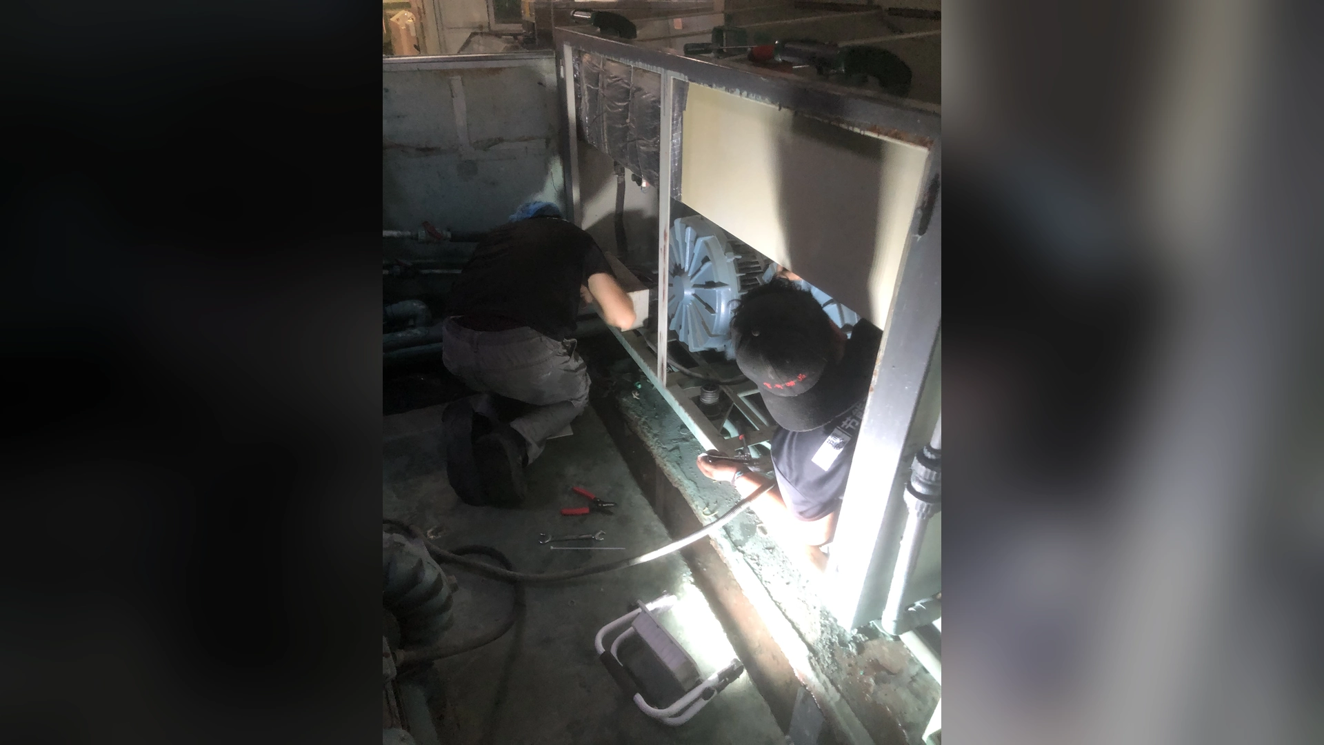
The safest way to shorten blower replacement downtime is to finish engineering before the shutdown. Measure the existing duty and interfaces, approve the replacement drawing, prefabricate brackets and adapters, verify electrical signals, assemble tools and spares, and write a timed installation and commissioning sequence.
Do not promise zero downtime unless a proven parallel or standby air path carries the full process. For most retrofits, the realistic goal is a short planned outage with clear hold points, acceptance criteria and a rollback option if the new blower cannot be commissioned within the window.
Downtime Is Usually Lost Before the Shutdown Begins
The physical blower swap may take only part of the outage. Projects run late because teams discover an incorrect centerline, missing connector, incompatible analog signal or untested adapter after production has stopped.
Downtime risk is reduced by moving uncertainty into the planning stage. Before the shutdown, the team should know:
- what airflow and pressure the process needs;
- which exact replacement model has been approved;
- how every mechanical and electrical interface will connect;
- which work can be completed while production is running;
- how performance will be accepted;
- when to stop and restore the original arrangement.
A detailed plan is more valuable than asking installers to “work faster.”
Establish the Real Scope
Clarify whether the project replaces only the blower or also changes:
- inlet filter and silencer;
- pipe sizes or routing;
- flexible connectors;
- valves and manifolds;
- mounting base;
- electrical protection;
- controller and PLC logic;
- cabinet ventilation;
- pressure and airflow instrumentation.
Each added change can improve the system, but it also adds shutdown tasks. Complete independent work in advance and isolate the critical path.
Measure the Existing System Before Removal
While production is stable, record:
- airflow and method;
- inlet, discharge and critical branch pressures;
- filter differential pressure;
- true electrical input, voltage and current;
- blower speed or controller setting;
- valve positions and active outlets;
- product, line speed and process result;
- temperature, vibration and alarms.
These readings define the air duty and the commissioning target. Motor nameplate power alone cannot do that.
Also measure mounting holes, port centerlines, connections, available envelope, cooling clearance and service access during an approved survey. Photograph every interface.
Freeze the Design Before Fabrication
The replacement supplier should confirm the selected operating point on the model-specific P–Q curve. Maximum airflow and maximum pressure are separate endpoints and do not occur simultaneously.
Approve:
- exact model and voltage version;
- duty-point performance and expected input power;
- final dimensional and connection drawing;
- inlet and outlet adapters;
- mounting base or bracket;
- filters and flexible connections;
- control and alarm interface;
- cooling and service clearance;
- factory-test scope;
- commissioning method.
Control document revisions. A late model or port-orientation change can invalidate prefabricated parts.
Prefabricate and Inspect Every Interface
Complete as much work as possible away from the running machine:
- manufacture and paint brackets;
- fabricate reducers or spool pieces;
- assemble hoses and connectors;
- prepare cables and labeled terminals;
- configure PLC logic offline;
- prepare pressure taps;
- inspect gaskets and fasteners;
- build guards and covers;
- verify lifting equipment.
Where practical, create a physical template or mock-up of mounting holes and centerlines. Dry-fit adapters to the new blower before shipment to the site.
Do not rely on flexible hose to correct major misalignment. It should not carry pipe weight or become a hidden restriction.
Factory Checks Reduce Site Risk
Before delivery, confirm the exact model, voltage, controller and accessories. Depending on project risk, request evidence for:
- functional running;
- speed-control range;
- alarm outputs;
- airflow and pressure at an agreed point;
- current or input power;
- connections and dimensions;
- noise or vibration observation;
- documentation and packaging.
A factory test cannot reproduce all site resistance, but it can catch configuration errors before the outage.
Test Controls Before the Shutdown
Electrical integration often becomes the critical path. Review the wiring diagram with the equipment controls team.
Confirm:
- voltage, phase and frequency;
- breaker and cable capacity;
- run/stop signal;
- analog or digital speed command;
- ready, running and fault outputs;
- speed feedback;
- alarm reset;
- interlocks and emergency stop;
- behavior after power loss;
- valve and speed sequencing.
Where safe and practical, bench-test the new controller and PLC interface. Simulate signals rather than waiting until the blower is installed.
Choose the Right Shutdown Window
Select a window based on process inventory, staff availability and recovery time—not simply the shortest gap in the schedule.
Plan for:
- safe process emptying or preservation;
- electrical and mechanical isolation;
- cooling time;
- access for lifting and fabrication;
- qualified mechanical, electrical and controls staff;
- supplier support availability;
- test product and utilities;
- contingency time;
- restart of upstream and downstream equipment.
Schedule critical work when decision-makers and technical support are reachable.
Write a Timed Job Sequence
A practical sequence may be:
- Confirm production release and permits.
- Record final baseline readings.
- Stop, isolate and verify zero-energy state.
- Label and disconnect electrical and controls.
- Disconnect pipework without losing evidence of strain.
- Remove the existing blower intact.
- Inspect and clean the base and air path.
- Install the prepared bracket and new blower.
- Connect independently supported pipe and flexible sections.
- Complete electrical and control wiring.
- Perform mechanical and electrical pre-start checks.
- Start at the approved initial setting.
- Check leaks, rotation or control direction, vibration and alarms.
- Measure airflow, pressure and input power.
- Test process output and normal recipes.
- Release production or execute rollback.
Assign an owner and planned duration to each step. Mark hold points that require engineering approval.
Preserve the Existing Blower for Rollback
Do not damage the old unit during removal unless disposal is certain and the new system has already been proven elsewhere. Protect openings from contamination and keep the old controller, cables, fasteners and adapters labeled.
Define the rollback trigger before the outage. Examples include:
- mechanical interface cannot be made safely;
- controls cannot communicate;
- required airflow or pressure cannot be reached;
- temperature, current or vibration is abnormal;
- process acceptance fails;
- commissioning exceeds the decision deadline.
Rollback is not failure. It is a risk-control option that protects production while the cause is corrected.
Can Production Continue During the Retrofit?
Only when an independent air source can safely carry the required process duty. Options may include:
- installed standby blower;
- parallel blower train;
- temporary rental unit;
- bypass air connection;
- staged work on duplicated lines;
- production transfer to another machine.
Temporary systems need the same engineering review as permanent systems: airflow, pressure, filtration, electrical supply, controls, hose restraint, noise and process safety.
Do not connect an improvised blower or compressor merely to avoid a shutdown. Excess pressure, contaminated air or unstable control can create greater loss than a planned stop.
Commission in Stages
Start with approved pre-start checks and a conservative initial setting. Confirm air path, mounting, electrical supply and cooling before full production.
Then verify:
- inlet and discharge pressure;
- airflow or representative outlet velocity;
- filter differential pressure;
- blower speed;
- voltage, current and true input power;
- leaks, noise and vibration;
- cooling and cabinet temperature;
- alarms and interlocks;
- process result at normal line speed.
Test minimum, normal and maximum production states. A blower that passes one recipe may not suit another.
Define Acceptance Before the Outage
The commissioning team should not debate success criteria while production waits. Agree in advance on:
- required process quality;
- airflow and pressure basis;
- measurement points and instruments;
- permitted operating range;
- electrical and temperature limits;
- control and alarm response;
- allowed deviation and corrective process;
- documentation required for release.
Factory and site readings may differ because of real system resistance. The acceptance plan should compare the installed duty, not catalogue maxima.
Applying the Plan to Towwind Blowers
For a short-shutdown retrofit, confirm the selected Towwind model’s released curve, electrical variant and final connection drawing before prefabrication. Catalogue endpoints do not establish the installed duty.
Confirm the delivered model’s motor, usable control range, protection, noise evidence, accessories and control interface from released documents. Installed sound and performance must be checked under actual site conditions.
Send Towwind measured site data and arrange technical-support availability during the planned commissioning window where project risk justifies it.
Energy Verification Without Extending Downtime
Prepare instruments, point labels and data sheets before the outage. Measure new input power only after process output is stable and equivalent to the baseline.
Calculate:
Annual energy use (kWh) = measured input power in each state (kW) × annual hours in that state
A short shutdown plan does not establish energy performance. Verify any reduction from the old blower’s measured input and the new system’s input at equivalent accepted duty, accounting for resistance, controls and actual operating hours.
Initial production release should prioritize safe, stable operation. Longer-term energy verification can continue after release using agreed monitoring, provided core acceptance is already satisfied.
Common Causes of Extended Downtime
- Incorrect mounting or centerline measurements.
- Adapters fabricated from a preliminary drawing.
- Missing electrical connectors or control relays.
- Unknown PLC signal range.
- Unsupported pipe that shifts after disconnection.
- Contaminated pipe requiring unplanned cleaning.
- No test product or instrument available.
- Supplier support unavailable across time zones.
- No agreed acceptance criteria.
- Old blower discarded before the new system is proven.
Each item can be addressed in planning.
Handover After Restart
Before closing the project, provide maintenance with:
- final as-built mechanical and electrical drawings;
- model and serial information;
- accepted airflow, pressure, power and temperature baseline;
- control parameters and backups;
- filter and spare references;
- alarm and troubleshooting guide;
- maintenance checklist;
- remaining corrective actions;
- warranty and support contacts.
Monitor the first production period and review data after filters and connections have settled.
Final Takeaway
Short blower retrofit downtime comes from preparation, not rushed installation. Measure the existing system, freeze the design, prefabricate every interface, test controls and define acceptance and rollback before production stops.
Where continuous air is essential, use an engineered standby or temporary system. Otherwise, plan a short, controlled outage with the right people, parts and evidence ready. This approach reduces both downtime and the risk of restarting with an unverified blower.
Frequently Asked Questions
Can a blower be replaced with zero production downtime?
Only if a proven independent or parallel air source safely carries the full process during the work. Otherwise, plan a controlled shutdown.
What should be completed before the shutdown?
Complete selection, drawings, adapters, brackets, cables, PLC logic, factory checks, tools, spares, permits, acceptance criteria and rollback planning.
Should the old blower be discarded immediately?
No. Preserve it and its interfaces until the replacement passes commissioning and production acceptance, unless safety or condition prevents reuse.
What commonly delays a blower retrofit?
Incorrect dimensions, preliminary drawings, missing electrical interfaces, pipe strain, unavailable instruments and undefined acceptance criteria are common causes.
When should energy savings be verified?
Record initial input after stable equivalent process output is achieved, then confirm across the real load profile without delaying safe production release unnecessarily.