
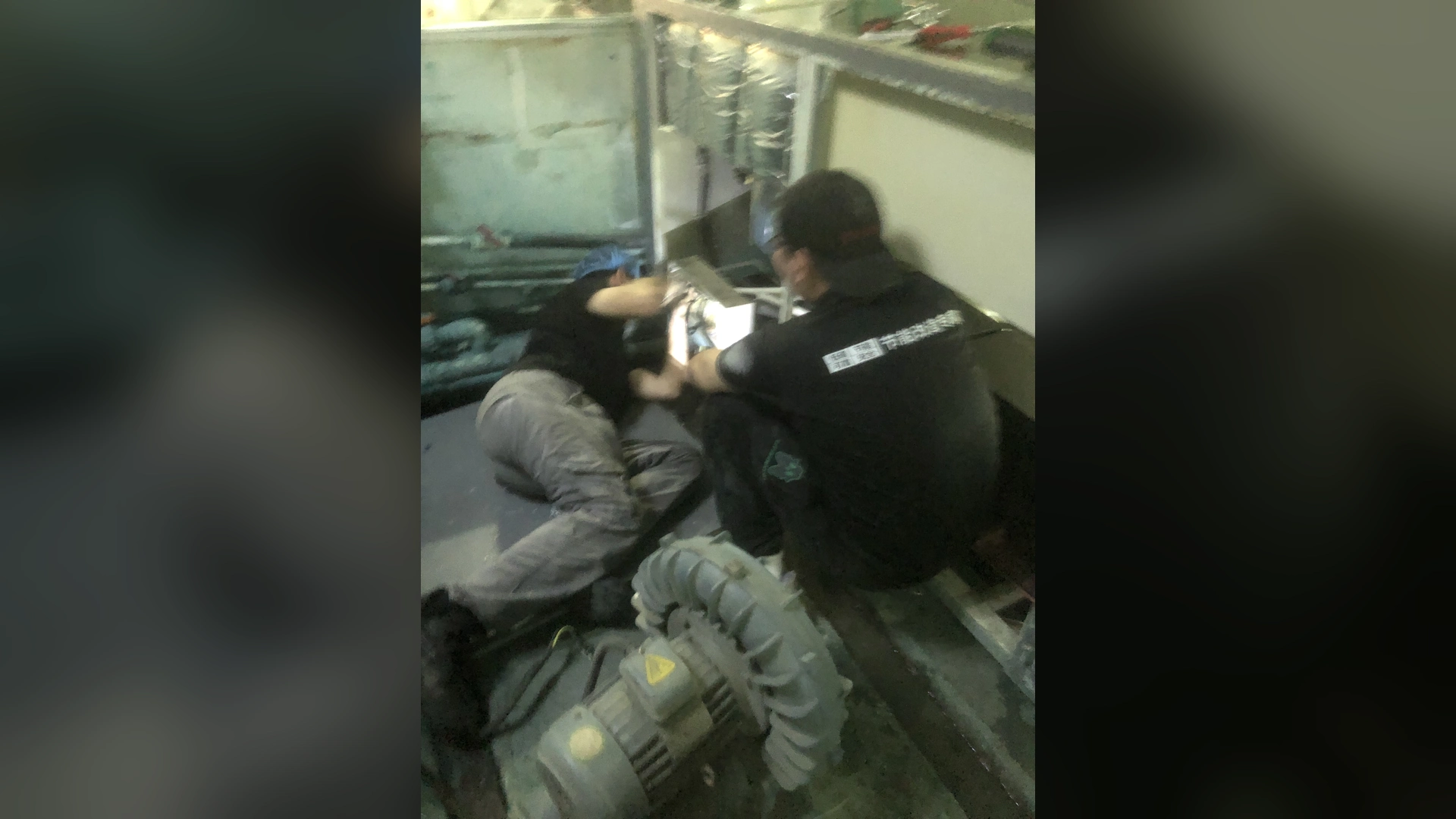
Before ordering a replacement blower, survey the interfaces that determine whether it can be installed and maintained: the mounting datum and hole pattern, package envelope, electrical supply, control signals, cable route, cooling clearance and service access. Record actual dimensions and connection evidence; do not assume the new unit will fit because its motor rating or nominal port size resembles the old one.
This is a blower replacement mounting and electrical interface survey, not a method for selecting airflow and pressure. Keep the existing operating-duty record as a separate input. Compare this site survey with the exact proposed model’s controlled drawing and manual before approving brackets, wiring changes or installation work.
Set the Boundary of the Interface Survey
The site team needs two different evidence packs. The operating-duty pack records airflow, pressure, true input power and process results under named production conditions. The interface pack records the physical and control connections that a replacement must fit. This guide covers the second pack. If the duty is not yet measured, obtain it separately before model selection rather than filling interface gaps with catalogue maxima.
The pipe-interface RFQ is also a separate task. Here, identify where inlet and outlet ports meet the existing installation and flag alignment or support constraints. Detailed pipe bore, fittings, pressure loss, adapter scope and reuse decisions need their own documented review.
Prepare a Safe Survey and One Measurement Datum
Gather the existing installation drawing, nameplate photograph, control schematic and any approved maintenance record. Mark each drawing as current, superseded or unverified. Plan access with the site team; measurements behind guards or at live terminals require the applicable isolation procedure and qualified personnel.
Choose one fixed datum, such as an existing base edge or machine reference line. Mark the datum on the sketch and photographs. Measure critical offsets from that reference instead of chaining several dimensions together. Record units, instrument, date and whether each value was measured, copied from a controlled drawing or estimated.
Measure the Mounting Base and Alignment
With the equipment safely isolated, record the base footprint, mounting-hole count and diameter, center-to-center spacing, slot length and width, fastener access, orientation and blower centerline height. Note adjustable brackets, anti-vibration mounts, base level and visible distortion. A slotted hole cannot be described by bolt spacing alone.
Photograph the base from at least two directions with the datum visible. If a bracket appears improvised or bent, record the condition rather than treating it as a dimension to reproduce. The replacement proposal should state whether the existing base can be reused, needs a reviewed bracket or requires a different installation plan.
Record the Package Envelope, Cooling and Service Access
Measure the available length, width and height around the installed blower, including door swing, guard removal, lifting route and tool access. Record the path needed to remove an inlet filter or open a controller cover. Mark nearby hot surfaces, cabinet vents and any location where discharge or cooling air could recirculate.
Do not prescribe a universal cooling clearance. Compare the actual site space with the selected model’s final installation manual. A package that physically fits but cannot be cooled, wired or serviced is not an acceptable fit.
Capture Electrical Supply and Control Interfaces
Qualified personnel should document the installed supply voltage, phase, frequency, protective device, grounding, cable size and available routing. Record terminal or connector type, cable entry location, cable bend space and access for safe maintenance. Do not infer electrical compatibility from the old motor nameplate alone.
Identify how the machine starts and stops the blower, commands speed, receives ready/fault signals and applies interlocks or emergency-stop logic. Record signal type and range, controller mounting, any communication protocol and the current alarm-reset behavior. Save a controlled schematic or permitted screenshots; label unknown signals instead of guessing.
Any required relay, controller or PLC change belongs in the retrofit scope before a purchase order is released. The equipment builder and qualified electrician must confirm the final design against the selected blower’s documentation.
Note Port Position and Pipe Strain Without Deciding Pipe Reuse
Record inlet and outlet orientation, mating connection type, port centerlines from the same datum, first fixed pipe position and existing supports. Photograph flexible sections and signs that the pipe is pulling on the blower. Do not force a new package into alignment by loading its ports or base.
These observations flag installation constraints; they do not prove that the existing pipework is hydraulically suitable. A separate pipe-interface RFQ and operating-point review must resolve bore, fitting losses, adapter design and any pipe-reuse decision.
Build a Measured Interface Register
| Interface | Site evidence to record | Replacement-side check |
|---|---|---|
| Mounting | Datum, footprint, hole or slot geometry, centerline and photographs | Exact-model controlled base drawing; bracket decision |
| Envelope | Available dimensions, access route, removable panels and lifting limits | Package envelope and installation sequence |
| Cooling and service | Ventilation path, nearby heat, filter-removal and controller access | Model-specific manual clearances and service requirements |
| Electrical supply | Verified voltage, phase, frequency, protection, grounding and cable route | Exact-model electrical and protection requirements |
| Controls | Run/stop, speed command, feedback, alarms, interlocks and signal ranges | Controller input/output schedule and integration changes |
| Port position | Orientation, centerlines, first fixed pipe and existing supports | Separate adapter and pipe-interface review |
For each critical entry, add an evidence status: measured, controlled drawing, estimated or unknown. Keep unresolved items visible. Do not copy a nominal dimension into the measured column or round a mounting location before bracket design.
Compare the Survey With the Exact Proposed Model
Ask the supplier for a controlled general-arrangement drawing, mounting and port details, electrical requirements, control interface schedule and model-specific cooling/service requirements. Compare each against the site register. Record the drawing revision and who approved each interface.
Stop the fit decision where a critical dimension, signal or clearance remains unknown. Do not fabricate brackets or adapters from an illustrative catalogue image. After installation, verify mounting, cable routing, cooling access and controls against the agreed drawing before the normal commissioning checks begin.
What to Send for a Replacement Interface Review
Send Towwind Technology or the selected supplier the dimensioned sketch, datum-marked photographs, interface register, current electrical/control drawings and the separately prepared operating-duty record. Ask for the exact proposed-model drawing, a written list of fit assumptions and the outstanding site measurements. The requested outcome is an approved installation-interface plan, not a promise that a replacement will fit every existing connection.
Frequently Asked Questions
Can the old blower nameplate establish installation compatibility?
No. It helps identify the existing equipment but does not establish mounting geometry, cable routing, control signals or required service clearance. Measure those interfaces directly.
Should mounting holes be copied from an old bracket?
Record the actual geometry and condition first. A distorted or improvised bracket may need a new design; compare the site datum with the exact replacement drawing before approving reuse.
Is a port photograph enough to approve pipe reuse?
No. The photograph helps document position and access. Pipe bore, losses, condition, supports and the replacement operating point require a separate engineering review.
When may brackets or adapters be fabricated?
After the exact proposed model’s controlled dimensions are issued and the responsible site team approves the interface and installation scope. Unknown dimensions must be resolved or explicitly assigned for measurement.