
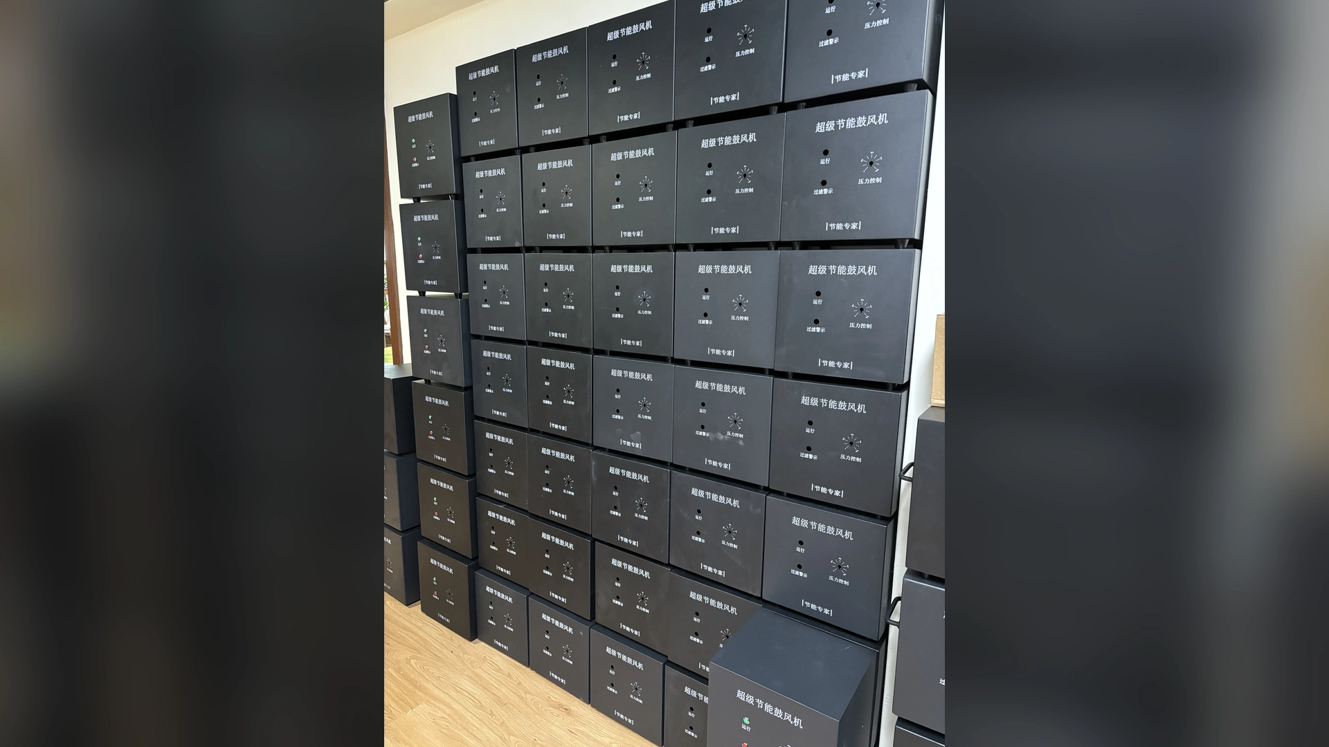
Reliable continuous operation begins with selecting the blower at the real airflow-and-pressure duty point, then protecting it with clean inlet air, adequate cooling, strain-free piping and stable electrical supply. Commission pressure, airflow, power, temperature and vibration baselines, and maintain them by operating hours and condition—not by memory.
For processes that cannot tolerate a stop, reliability also requires a recovery plan: alarm integration, critical spares, safe isolation and, where justified, a tested standby blower. A premium component cannot compensate for an installation that runs at the wrong point or cannot be serviced.
Reliability Starts Before Purchase
Many blower failures are shaped during specification. A supplier cannot confirm continuous duty from motor power alone. It needs the required airflow, total pressure, speed range, duty cycle, ambient conditions and process consequences of a trip.
Provide:
- normal and maximum airflow and pressure states;
- operating hours and uninterrupted run length;
- number of starts and stops;
- filter, pipe, manifold and terminal-device information;
- ambient temperature, altitude, humidity and contamination;
- voltage, phase and control signals;
- cabinet arrangement and cooling method;
- acceptable downtime and recovery time;
- maintenance windows and staff capability.
This information lets the buyer compare complete solutions instead of nominal motor sizes.
Select at the Real Operating Point
A blower works where its performance curve intersects the system-resistance curve. Filters, pipework, valves, manifolds and air knives or diffusers establish that resistance.
Maximum airflow and maximum pressure are separate endpoints and do not occur together. Plot the required airflow and pressure on the model-specific curve and confirm continuous-duty suitability, input power, speed and operating margin at that point.
Check every important production state. A high-flow state with several open outlets may load the blower differently from a high-pressure state with valves closed. The selection must remain within approved limits throughout the operating range.
Use reasonable margin for normal filter loading and process variation, but avoid excessive oversizing. A large blower controlled mainly by throttling can waste energy and create difficult low-demand operation.
Design the Air Path for Low, Predictable Resistance
Reliable operation depends on the system staying close to its intended resistance curve. Avoid undersized pipes, abrupt transitions, unnecessary flexible hose and repeated sharp bends.
Support pipework independently so its weight and misalignment do not load the blower connections. Use suitable flexible connectors where specified, but ensure they cannot collapse under inlet vacuum or twist during installation.
Provide pressure taps around filters and other important restrictions. These points allow maintenance to find a developing problem without dismantling the system or replacing the blower by guesswork.
Protect Process and Cooling Air
An inlet filter keeps dust and debris out of the blower and downstream process. Select it for the contaminant, required flow and allowable pressure drop. Include both clean and expected loaded loss in the duty calculation.
High-speed blowers may also have a separate cooling-air path. Dust on vents, fans or heat-transfer surfaces can raise temperature even when the main process filter is clean.
Set filter inspection and service intervals from the selected model manual, measured differential pressure, operating hours and site contamination; do not assume a universal calendar interval.
Keep Cooling Air Clean and Moving
Continuous operation creates a steady heat load. Preserve the manufacturer’s required clearance around vents, heat sinks, filters and service covers. Prevent stored material or later acoustic treatment from occupying that space.
Check for hot-air recirculation inside enclosures. Cabinet ventilation must remove heat from the blower and every other installed electrical device under the hottest credible ambient condition.
Measure cooling-intake and cabinet temperature during full production. Room temperature alone can miss a local hot zone. At altitude, lower air density may require supplier review.
Stabilize Electrical Supply and Control Logic
Confirm the exact voltage, phase and frequency for the model. Verify cable sizing, protection, grounding and controller wiring under applicable standards and the final manual.
For three-phase systems, record relevant phase values and investigate imbalance. For BLDC or other electronically controlled blowers, use the approved measurement procedure and preserve controller fault codes.
Control logic should avoid unnecessary rapid cycling, unintended valve closures and abrupt recipe transitions. Test the sequence that follows a power interruption or alarm. The production line must enter a safe state when airflow is lost.
Establish a Commissioning Baseline
The first accepted production run is the reference for future maintenance. Record each major operating mode after conditions stabilize:
- airflow and measurement method;
- inlet, discharge, header and critical branch pressures;
- filter differential pressure;
- blower speed or command;
- voltage, current and true input power;
- ambient, cooling-intake and cabinet temperatures;
- valve positions and active outlets;
- vibration or repeatable sound data;
- product, line speed and acceptance result;
- instrument and measuring locations.
Photograph filters, clearances, flexible connections and gauge points. Baseline data turns a later complaint into a measurable change.
Monitor Trends, Not Isolated Numbers
A single reading can remain inside a limit while moving steadily toward a problem. Trend data at comparable production states.
Useful patterns include:
- rising filter differential with falling airflow;
- increasing speed needed for the same process result;
- rising temperature at unchanged load;
- increasing vibration or new mechanical tones;
- greater power at equal airflow and pressure;
- one branch weakening while total header data remains stable;
- repeated controller warnings before a trip.
Set alarms using manufacturer limits and observed normal variation. An alarm that is too sensitive causes nuisance stops; one set without reference to equipment limits may react too late.
Make Preventive Maintenance Model-Specific
A generic “check blower” line is not enough. The checklist should identify what, where and how to inspect, including:
- filter element and differential pressure;
- cooling vents, cabinet filters and fans;
- pipe supports, flexible connectors and leaks;
- mounting fasteners and alignment;
- pressure and airflow readings;
- speed, current and input power;
- temperature, vibration and noise;
- alarm and event history;
- service clearance and housekeeping.
Use operating hours and start count where relevant. Record findings and corrective actions. Do not dismantle protected assemblies or lubricate bearings unless the model manual provides an approved procedure.
Correct Small System Problems Early
Operators often compensate for deterioration by increasing speed. This can maintain production temporarily while adding thermal and electrical load.
When a speed setting rises for the same product, investigate:
- dirty filters;
- blocked air-knife slots or diffusers;
- valve movement;
- crushed hoses;
- leakage;
- changed product position or line speed;
- cooling-air restriction;
- measurement drift.
Restore the system before increasing the blower’s permanent duty. Early correction is less disruptive than a high-temperature trip during full production.
Plan Spares Around Failure Consequence
Critical spare strategy should reflect lead time, fault probability and production loss. Possible items include filters, controllers, sensors, flexible connectors or a complete blower, depending on the model and site repair capability.
A spare stored without preservation, correct software parameters or connection hardware may not provide rapid recovery. Keep identification, storage requirements and test procedures documented.
Ask suppliers which components are field-replaceable, which require factory service and what evidence is needed for support. Consider customs and transport time for international sites.
Use Redundancy Where the Process Justifies It
A standby blower can reduce downtime for critical aeration, cooling or continuous drying, but redundancy must be engineered.
Verify:
- isolation and nonreturn arrangements;
- shared filter and pipe capacity;
- standby protection from contamination;
- electrical and control capacity;
- automatic or manual changeover logic;
- periodic test schedule;
- process behavior during transition;
- whether one unit can truly carry the required duty.
A standby connected to the same blocked air path does not solve a system fault. Parallel blowers also interact through their curves and require engineering review.
Respond to Alarms Without Destroying Evidence
Before resetting, where safe, save:
- alarm code and time;
- speed command and feedback;
- pressures and airflow;
- current or true input power;
- temperatures;
- valve and filter condition;
- product and line state;
- recent maintenance or parameter changes.
Repeatedly clearing a fault can remove the sequence needed for diagnosis. Escalate recurring trips, overheating, abnormal current, unusual vibration or unexplained performance loss to qualified technical support.
Applying This to Towwind Energy-Saving Blowers
Confirm the selected model’s current specification, pressure-flow curve, electrical nameplate and installation requirements before assigning an operating point.
Confirm the selected model’s current specification, pressure-flow curve, electrical nameplate and installation requirements before assigning an operating point.
For a continuous-line recommendation, send Towwind the full duty range, operating schedule, ambient and contamination data, voltage, cabinet arrangement, controls, available space and downtime consequence. Confirm the exact model through its final manual and connection drawing.
Reliability and Energy Cost Belong Together
Energy improvements should not reduce operating margin or maintenance access. Compare systems at equal production output using measured true input power:
Energy use (kWh) = measured input power (kW) × operating hours
For varying recipes, calculate each state separately. Include auxiliary cooling and standby energy where material.
Evaluate energy and downtime separately using site records. Any energy benefit depends on the existing system, duty, controls and production schedule.
A Buyer’s Reliability Checklist
Before placing the order, confirm:
- continuous-duty approval at every required operating point;
- ambient, altitude and cooling limits;
- inlet filtration and loaded pressure loss;
- electrical and control interfaces;
- alarm outputs and retained fault history;
- installation clearance and pipe-load limits;
- maintenance tasks and intervals;
- service parts, lead times and support process;
- commissioning and acceptance-test method;
- standby or recovery plan for critical production.
Written confirmation reduces the gap between a successful purchase test and dependable years of operation.
Final Takeaway
Blower reliability in continuous production is built as a system. Correct selection prevents operation outside the useful range. Clean air and cooling protect components. Good piping avoids mechanical strain. Baseline monitoring and model-specific maintenance reveal deterioration early.
For critical lines, add alarm discipline, spares and tested recovery arrangements. These measures cost less than treating every production stop as an isolated blower failure and give buyers a realistic path to lower lifetime cost.
Frequently Asked Questions
What is the most important factor in continuous blower reliability?
Correct selection at the real duty point is the foundation. Cooling, filtration, installation and maintenance then determine whether that capability is preserved.
Does a larger blower improve reliability?
Not automatically. Excessive oversizing can create inefficient throttling and unsuitable low-demand operation. Select from the full operating range.
What data should be trended?
Trend airflow, tagged pressures, filter differential, speed, true input power, temperature, vibration, alarms and process output at comparable operating states.
Is a standby blower always necessary?
No. Its value depends on downtime consequence and recovery time. Critical processes may justify redundancy, but the changeover and shared air path must be engineered and tested.
When should technical support be contacted?
Escalate recurring trips, overheating, abnormal current, increasing vibration, unusual mechanical noise or performance loss that remains after external system checks.