
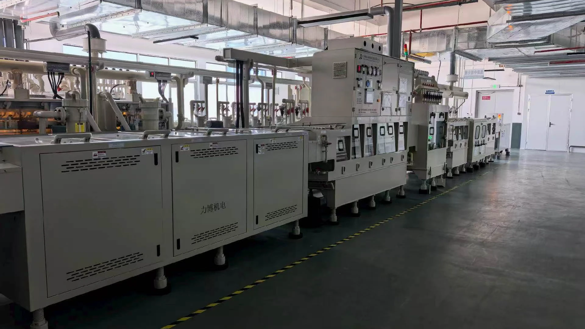
For a buyer, the practical objective is not simply to purchase an “energy saving” motor. It is to supply the air knives at the airflow and pressure needed to remove water from the actual PCB, at the required line speed, throughout the expected production range. The proposed blower must also fit the machine, match the electrical supply and provide controls that the line PLC can use.
Quick Answer
Select a PCB air knife blower from the installed operating point, not from maximum airflow, maximum pressure or the power rating printed on the old nameplate. Record the number of air knives operating together, slot dimensions, manifold arrangement, pipe losses, conveyor speed, board mix and current drying result. Then compare those requirements with a blower curve and confirm the result in a wet-board trial.
Request current released data for the exact Towwind model and electrical variant before shortlisting. The correct candidate must meet simultaneous airflow and pressure at the installed duty, allow a justified margin and support the validated production recipe.
Why PCB Air Knife Duty Is Different from Open Blow-Off
An air knife converts supplied air into a high-velocity sheet. In a horizontal PCB line, several knives may be positioned above and below the conveyor, often at angles chosen to push water away from holes, edges and component features. The blower does not see an open pipe. It sees resistance from the inlet filter, ducting, bends, branches, manifold and narrow knife slots.
Small changes can move the duty point. Closing one branch raises resistance. Widening a slot may lower pressure but demand more flow. Adding a second drying section can increase simultaneous demand. A filter that gradually loads during production changes the inlet condition. Therefore, a model that works during a brief test with one clean knife may not represent the complete machine.
The process target also matters. “Board feels dry” is too vague for purchasing or acceptance. Define the board type, conveyor speed, water temperature if relevant, knife arrangement and inspection method. Critical locations may include through-holes, panel edges, tooling holes and areas shielded by fixtures. Where a downstream process is sensitive to residual moisture, agree on that process requirement before approving the blower.
Start with the Installed Air System
For an existing line, measure before removing the current blower. Useful records include:
- static pressure at the blower outlet and at the air-knife manifold;
- airflow, if a suitable test point and method are available;
- real electrical input in normal production, preferably logged over a complete cycle;
- conveyor speed and the PCB types run during the measurement;
- which knives and valves are open in each recipe;
- filter condition, pipe sizes, hose lengths, bends and reducers;
- visible water remaining after each drying stage; and
- alarms, temperature, noise and maintenance history.
If airflow cannot be measured accurately, do not invent it. The existing pressure, piping details, slot geometry and verified drying result still provide valuable evidence. A controlled trial with the proposed blower can close the remaining gap.
For a new machine, the equipment builder should provide a layout rather than a single desired pressure. List every simultaneous knife, its slot length and width, the branch connection, main duct size and approximate run. Also identify the most demanding board and target speed. This gives the blower supplier enough information to check the whole air path.
Read Airflow and Pressure Together
Maximum airflow and maximum pressure are endpoints of a blower curve. They normally occur under different conditions and cannot be added together as though both were available at once. Once connected, the blower operates where its performance curve meets the system resistance curve.
This point explains many disappointing substitutions. A buyer may compare a proposed model’s maximum flow with the old model’s catalogue flow and assume it is equivalent. Yet the proposed unit may deliver a different flow at the manifold pressure required by the knives. The opposite mistake is to compare only maximum pressure even though the system needs substantial volume across several slots.
Ask for the applicable pressure-flow curve and mark the expected duty on it. If the line has multiple recipes, mark the low, normal and demanding conditions. The selected model should operate within its permitted region rather than at an unverified catalogue endpoint. Allow practical margin for normal filter loading and production variation, but do not use excessive margin as a substitute for missing data.
Towwind Models for Initial Screening
For a proposed Towwind model, request its released curve, electrical and control data and final installation drawing. Verify the combined knife duty and wet-board result; this article does not establish model ratings or PCB drying capability.
Confirm the selected model’s control range, electrical supply, environmental rating, certification, noise and dimensions from current released documentation. Adjustable output does not replace a verified pressure-flow match.
Supplier data alone cannot establish PCB drying performance. Require the exact curve at the combined duty and verify the result on wet boards across representative production modes.
Use Adjustment as a Process Tool
Variable output is valuable when a PCB line handles different panel sizes or speeds. The commissioning team can begin at a conservative setting, confirm water removal, then reduce output until the process approaches its limit. The production setting should include a controlled margin above that limit.
This method is more defensible than running permanently at maximum output. It also creates recipes for light and demanding products. However, control must be deliberate. Record the command method, minimum permitted setting, ramp behavior and what happens when the PLC signal is lost. Operators should not be able to reduce air below the validated recipe without an appropriate warning or access control.
Where the blower provides alarm or status interfaces, agree on the signal type and PLC logic before manufacture. A general machine alarm is not enough if maintenance cannot tell whether the cause was supply loss, overtemperature, overload or another protective event. The delivered manual and wiring diagram must govern the final connection.
Mechanical Integration Checks
Space inside a PCB machine is often tight, but the blower needs more than an outline clearance. Its cooling air path must remain open, and the inlet filter must be reachable without dismantling the dryer. Leave room to inspect connections and remove the unit for service.
Do not use rigid pipework to force the blower ports into alignment. Support the duct independently and use an appropriate flexible connection so pipe strain and vibration are not transferred to the casing. Check that reducers, tight elbows and undersized hoses do not consume the pressure margin saved by a compact installation.
The inlet should draw clean, dry air suitable for the machine environment. Protect it from chemical mist and process water. Arrange the outlet system to prevent liquid from draining back into the blower during shutdown or cleaning. If check valves, relief devices or drains are required, specify their orientation and maintenance access in the final design.
What Procurement Should Request
A comparable quotation needs more than a model number and unit price. Ask each supplier for:
- the proposed model and exact voltage variant;
- the pressure-flow evidence used for the selection;
- stated assumptions about simultaneous knives and system loss;
- current, protection, cable and grounding requirements;
- control input and alarm interface details;
- dimensions, port sizes, weight and service clearance;
- included filter, connectors and other accessories;
- warranty scope, spare-part route and technical response process; and
- the proposed test and acceptance conditions.
These items expose hidden differences between proposals. One quotation may exclude the inlet filter or control interface. Another may be based on a clean, open outlet rather than the installed manifold. A slightly higher purchase price can be the lower-risk choice if the duty evidence and support package are complete.
Commission with Wet Boards, Not Just Instruments
Commissioning should combine engineering measurements with the production result. First confirm supply voltage, phase, frequency, protective devices, grounding, rotation or control behavior as applicable, inlet clearance and unobstructed piping. Then start at a controlled setting and check for abnormal sound, vibration, heating, leakage and alarms.
Run representative wet boards at the agreed production speed. Inspect defined critical locations, not only the easiest flat surface. Record blower setting, outlet and manifold pressure, electrical input, conveyor speed, open branches, filter condition and ambient conditions. If several recipes are required, test each one.
Keep the accepted readings as the maintenance baseline. A later loss of drying performance can then be compared with known-good pressure, power and settings. For instance, unchanged blower power with lower manifold pressure may point toward leakage, while rising restriction may indicate a loading filter or obstructed air path. Baseline data shorten troubleshooting and help prevent unnecessary blower replacement.
Energy Savings Must Be Measured at Equal Output
Energy savings for a PCB air-knife system must be measured at equal accepted drying quality and throughput. Record the old and proposed system boundaries, actual operating points, controls and hours before calculating a site-specific result.
Compare measured kilowatt-hours while producing the same accepted result. Use the same board mix, line speed, active knives and inspection standard wherever possible. If the process varies, log both systems over representative production and normalize the comparison. Nameplate kilowatts alone do not show actual input or useful air delivered.
Annual energy use can be estimated as average measured input power multiplied by annual operating hours. Monetary saving equals the verified kWh reduction multiplied by the applicable electricity tariff. State whether demand charges, maintenance savings or downtime costs are included; otherwise, readers cannot reproduce the business case.
Final Buying Decision
An energy saving blower can be a strong fit for a PCB air knife system when its output is matched to the installed resistance and verified against a defined drying result. The best proposal will connect five things: the duty point, the air-path layout, the product mix, the control method and a practical acceptance test.
Send Towwind the knife dimensions, number operating together, duct and manifold layout, current pressure and power readings, conveyor speed, board details, electrical supply and available installation space. With that information, the supplier can screen the model family and identify what still requires a curve check or site trial. That is a safer route than choosing by rated kilowatts—and a far better basis for claiming an energy saving.
Frequently Asked Questions
Which Towwind blower is best for a PCB air knife system?
There is no universal model. Select an exact candidate only after checking simultaneous airflow and pressure, the active knives, installation interfaces and wet-board acceptance.
Can maximum airflow and maximum pressure be used together?
No. They are separate endpoints on the performance curve. Request the curve or verified duty data for the pressure and airflow the installed system needs simultaneously.
Is a 380 V blower always more powerful than a 220 V blower?
No. Within each Towwind family, the voltage identifies the supply variant. Model output and the actual operating point determine suitability; site voltage, phase, protection and current must also be checked.
How should energy savings be verified on a PCB line?
Measure electrical input over representative production while both systems achieve the same conveyor speed and accepted drying result. Include the same knife arrangement and comparable operating conditions.
What information should be sent for a blower recommendation?
Provide knife slot dimensions, quantity operating together, pipe and manifold layout, pressure and power readings, board mix, line speed, operating hours, voltage, controls, available space and the present drying problem.