
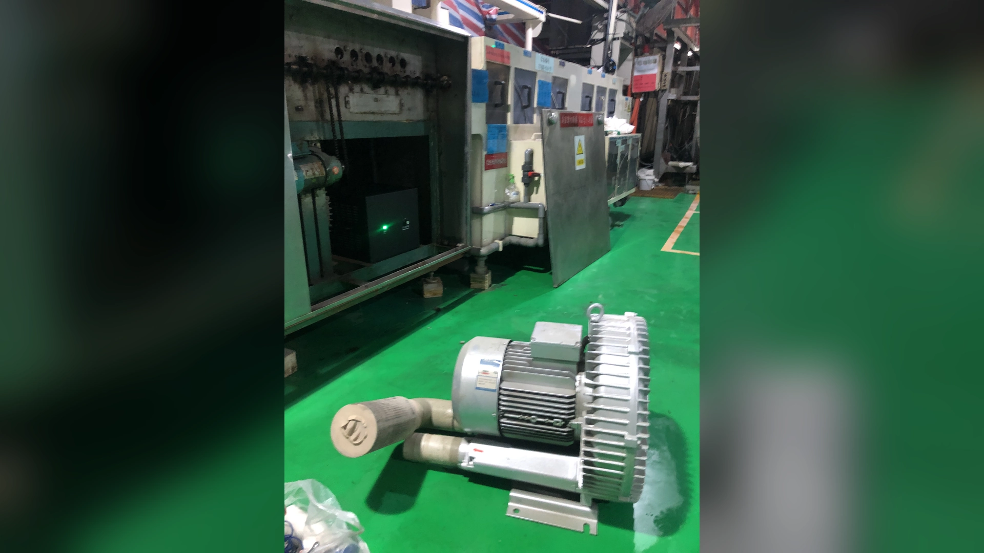
Before concluding that a blower underperforms, identify the rated point, the system operating point and the measurement basis. Airflow without pressure and conditions is incomplete.
Quick Answer
Actual airflow is determined by the intersection of the blower curve and the installed system resistance. Filters, pipe length, diameter, bends, valves, branches and terminal devices shift that point. Speed, air density, voltage, control limits and measurement method can create further differences.
Compare simultaneous airflow and pressure with the exact model curve. Use the same reference conditions and units, verify instruments, and record filter and valve condition. Maximum airflow should not be expected when the system also requires meaningful pressure.
What “Rated Airflow” Can Mean
Rated airflow may refer to several different values:
- maximum airflow at or near minimal pressure;
- airflow at a named pressure point;
- a nominal catalogue value;
- a tested value at specified speed and air condition; or
- airflow corrected to standard or normal conditions.
Read the curve notes and test basis. A single value copied from a table can lose the conditions that make it meaningful.
Ask the supplier whether flow is stated at the inlet, outlet or a reference condition.
Maximum Airflow Is a Curve Endpoint
The maximum airflow value is usually measured near the low-pressure end of the performance curve. As system resistance increases, the operating point moves and delivered airflow changes.
Maximum pressure is found at another endpoint, often at very low flow. Maximum airflow and maximum pressure do not occur together.
Selecting a blower by maximum flow alone is therefore unreliable for an air knife, aeration diffuser or piped process.
The System Determines Actual Flow
Every air path has a resistance curve. Pressure loss increases with airflow through filters, pipe, fittings, valves, manifolds and terminals.
The blower provides one curve; the system provides another. Their intersection is the actual operating point.
Changing pipe, valve position or terminal gap changes the system curve even though the blower remains the same.
Inlet Filter Loss
A clean filter has a pressure drop, and loading increases it. If the catalogue test used a clean, low-loss inlet but the site filter is smaller or dirty, actual airflow can be lower.
Measure differential pressure across the filter under production load. Inspect the grille and silencer as well.
Use condition and the final manual to set service intervals. Do not remove required filtration merely to approach a catalogue airflow number.
Pipe Diameter and Length
Small internal diameter creates higher velocity at a given flow and usually increases friction. Longer routes accumulate more loss.
Use actual internal dimensions, not nominal labels. Flexible hose, adapters and valves can contain a smaller passage than the main pipe.
Calculate each section according to the airflow it carries, especially before and after branches.
Elbows, Reducers and Valves
Tight elbows, tees, abrupt transitions and partly closed valves add local resistance. Several fittings close together can create disturbed flow beyond a simple visual estimate.
Measure pressure before and after suspicious components. Correct unnecessary restrictions before selecting a larger blower.
A throttle valve can raise upstream pressure while reducing airflow, so the gauge may look strong even when delivery is low.
Air Knives, Nozzles and Diffusers
Terminal devices deliberately convert pressure into velocity or distribute air. Slot length and gap, nozzle area and diffuser resistance are part of the operating point.
A wider air knife gap can demand more flow. A contaminated slot may change distribution. Additional active terminals divide the available capacity.
Record terminal configuration with every airflow measurement.
Leaks and Unintended Demand
A leak increases total airflow demand but reduces useful delivery at the process. An opened spare branch or damaged manifold end can have the same effect.
Inspect clamps, flexible connectors, gaskets, branch plugs and terminal seals. Repair leaks and rebalance the system.
Remeasure after repair because the blower operating point will move.
Blower Speed
Airflow changes approximately with speed for the same blower under similar conditions. A controller command below maximum, incorrect analogue scaling or a capped recipe can explain lower site flow.
Record commanded and actual speed where available. Check ramp, limits and alarm history.
Never increase speed beyond the final manual to match a free-air rating.
Electrical Supply and Rotation
Low voltage, phase problems, incorrect frequency settings or wrong rotation on applicable equipment can reduce performance or trigger protection.
Qualified personnel should verify supply under load. Compare with the installed nameplate rather than a similar model.
Towwind’s referenced range includes 220 V single-phase and 380 V three-phase versions with 50/60 Hz compatibility; exact wiring and settings remain model-specific.
Air Density and Temperature
Volumetric airflow, mass airflow and pressure behavior depend on air density. Density changes with temperature, altitude and absolute pressure.
A hot enclosure or high-altitude site may not reproduce factory test conditions. Determine whether the rated airflow is actual volume at test conditions or corrected standard volume.
Do not compare m3/h, standard m3/h and mass flow without conversion and a stated reference.
Measurement Location
Flow near the blower outlet may be turbulent and nonuniform. An elbow or valve can distort the profile. A single velocity reading at the duct centre does not necessarily represent area average.
Use a suitable straight section and recognized traverse or flow method where possible. Document internal area, probe position and orientation.
At an air knife outlet, entrainment and probe distance make local velocity different from total blower flow.
Instrument and Unit Errors
Check calibration, zero, range and units. m3/h, m3/min and CFM are common sources of error. Pressure units such as Pa, kPa, mbar and mmH2O can also be confused.
Compensate for density when the method requires it. Confirm whether the instrument reports actual or standardized flow.
Record enough information for another engineer to reproduce the result.
Manufacturing and Test Tolerance
Blower curves and measurements have tolerances. Instruments, production units and air conditions also vary.
Ask the supplier for the applicable test standard, tolerance and reference condition when the difference is commercially important. Avoid treating a curve line as infinitely precise.
A small deviation within combined uncertainty should not be diagnosed as a fault without further evidence.
Applying Towwind Product Data
A catalogue maximum airflow is not the installed flow. For any proposed Towwind model, use the released pressure-airflow curve at the site’s actual resistance and confirm measurement conditions before comparing rated and actual values.
These endpoints are separate. Site airflow through a pressurized system should be checked on the exact P-Q curve.
Actual airflow can also vary with the approved controller setting. Confirm the selected model’s usable control range, final curve and test basis; a command percentage is not itself a measured flow rate.
A Fair Comparison Procedure
- Identify the exact blower model and curve.
- Confirm rated airflow definition and reference conditions.
- Record simultaneous site airflow and pressure.
- Verify speed, electrical supply and rotation.
- Inspect filter, valves, branches, leaks and terminals.
- Document air temperature, altitude and density basis.
- Review instrument calibration and measurement location.
- Plot the site point on the exact curve.
- Correct external restrictions before judging the blower.
- Repeat the test and preserve the accepted baseline.
This procedure separates a real performance fault from a comparison-basis error.
When Lower Flow Indicates a Problem
Investigate when airflow falls from a known baseline at the same pressure, speed and process condition. Filter loading, blockage, leak, valve movement, control change or internal damage may be responsible.
Record current, real power, temperature, sound and alarms. Stop for abnormal heat, smell, severe vibration or mechanical noise.
Contact technical support with measurements rather than only stating that the blower “does not reach rated flow.”
Energy Implications
More airflow is not always more efficient. The process should receive the required amount, not the catalogue maximum. Excess flow can be throttled or bypassed at continuing energy cost.
More airflow is not always more efficient. The process should receive the required amount, not a separate catalogue maximum. Verify any saving at equivalent accepted output using measured real power and operating hours.
Correct system restrictions and measurement errors before making a replacement comparison.
What to Send a Supplier
Provide the rated value and source document, exact model, speed, pressure and airflow readings with locations, air temperature, altitude, filter condition, pipe layout, valves, branches, terminal data, electrical supply and measurement method.
Include product, line speed and process result. State whether flow is actual or standardized.
This lets the supplier reconstruct the operating point and explain any valid difference.
Conclusion
Rated and actual blower airflow differ when the rating and installation describe different pressure, air condition, speed or measurement basis. The real system curve—not the maximum airflow label—sets the installed operating point.
Compare simultaneous pressure and airflow under documented conditions. Once filters, piping, terminals, controls and measurement are aligned, buyers can judge performance fairly and avoid replacing a healthy blower for a misunderstanding of the rating.
Frequently Asked Questions
Why is actual airflow lower than the catalogue maximum?
The catalogue maximum is usually a low-pressure endpoint. Real filters, piping and terminals add resistance and move the operating point.
Can actual airflow be higher than a rated point?
It may differ if speed, pressure, air condition or reference basis differs. Verify the exact curve and permitted operating range.
Does a dirty filter reduce airflow?
Yes. Increased inlet pressure loss can shift the operating point and reduce delivery. Measure filter differential pressure under load.
Can I calculate airflow from one velocity reading?
Usually not reliably in a nonuniform duct. Use an appropriate traverse or validated flow method and the actual internal area.
What must match for a fair airflow comparison?
Match model, speed, pressure, air conditions, filter and valve state, branch configuration, units, reference basis and measurement method.