
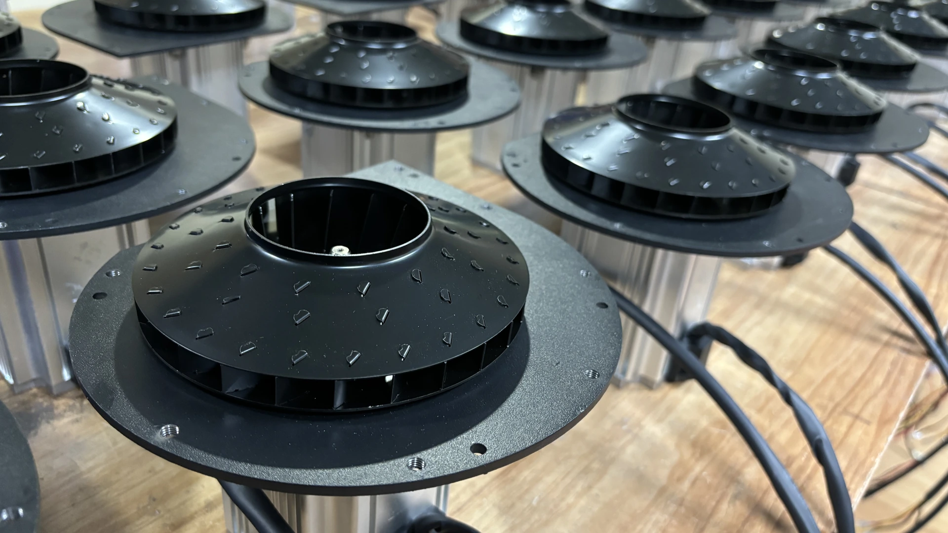
Two blowers with different impeller diameters cannot be compared fairly from diameter alone. Blade geometry, width, clearances, rotational speed, motor and controller, casing shape and operating point all influence the final result.
Quick Answer
For geometrically similar blowers operating under comparable conditions, an increase in impeller diameter generally raises airflow, pressure and power requirement. The diameter affinity relationships indicate approximate trends, but they apply only within similarity assumptions and cannot replace the manufacturer’s tested P-Q and power curves.
Equipment buyers should select a complete blower at the required simultaneous airflow and pressure. Users should never fit a different impeller, machine an impeller or exceed rated speed unless the original manufacturer has engineered and approved the change.
What Impeller Diameter Means
Impeller diameter normally refers to the outer diameter of the rotating air-moving element. The outer edge travels faster than the hub, so diameter influences peripheral or tip speed.
Tip speed can be expressed as:
Tip speed = π × impeller diameter × rotational speed
Use consistent units. If diameter is in metres and rotational speed is in revolutions per second, tip speed is in metres per second.
This equation describes motion at the edge. It does not by itself calculate delivered pressure, airflow, efficiency or sound.
Diameter Changes Tip Speed at the Same RPM
If two impellers rotate at the same RPM, the larger diameter has higher tip speed. Higher tip speed can transfer more energy to the air, provided blade geometry, casing and mechanical design support it.
However, the larger rotating assembly also experiences different stress and inertia. Bearings, shaft, balance, motor torque, controller and containment must be designed as a system.
That is why a field modification based on diameter alone is unsafe. The casing and motor of one model are not automatically suitable for another impeller.
Diameter Affinity Relationships
For geometrically similar blowers at the same speed and comparable air density, ideal similarity suggests:
Airflow varies approximately with diameter cubed
Pressure varies approximately with diameter squared
Power varies approximately with diameter to the fifth power
These relationships show that a modest diameter change can have a large theoretical effect on power. They are engineering scaling tools, not guaranteed performance predictions for unrelated products.
Similarity must include more than the outside diameter. Blade angles, widths, clearances, inlet, outlet and casing proportions must scale appropriately.
An Illustrative Diameter Change
If a geometrically similar impeller diameter increased by 10% at the same speed, ideal scaling would suggest approximately:
- airflow: 1.1³, or about 1.33 times;
- pressure: 1.1², or about 1.21 times; and
- power: 1.1⁵, or about 1.61 times.
The example explains why “slightly larger” does not mean “slightly more power.” It is not a Towwind performance prediction and should not be used to modify equipment.
Actual curves may differ because efficiency, flow passages and mechanical limits change.
Impeller Diameter and Airflow
A larger geometrically similar impeller can move more volume at the same speed, but the connected system determines the actual operating point. Filters, pipe, valves and terminals resist the flow.
Free-air maximum flow is not the same as production airflow through an air knife or aeration network. As system resistance rises, the blower operates at a different point on its P-Q curve.
Measure or calculate the required airflow at the process, then include distribution losses before selecting a model.
Impeller Diameter and Pressure
Pressure capability is related to the energy transferred to the air and therefore to impeller speed and geometry. Diameter can support higher tip speed, but blade design and casing conversion are equally important.
A larger diameter does not guarantee higher useful pressure at the process. An undersized pipe, dirty filter or throttle valve may consume the extra pressure before it reaches the terminal.
Specify pressure at a named location and airflow. Maximum pressure with the outlet effectively closed is not the same duty as pressure at production flow.
Impeller Diameter and Power
The steep theoretical relationship between diameter and power is one reason blower manufacturers design motor, controller and impeller together. A larger impeller can exceed motor current or thermal capability even when it physically fits.
Actual input power depends on operating point and efficiency. Motor nameplate power is not a measured consumption value, and two motors with the same rating can drive blowers with different curves.
Qualified personnel should measure real input, phase current where applicable and temperature during commissioning.
Speed and Diameter Work Together
Similar performance may sometimes be approached through different combinations of diameter and speed. A smaller high-speed impeller can produce a compact blower, while a larger impeller may operate at a lower RPM for another design objective.
Neither arrangement is automatically more efficient or reliable. Tip speed, aerodynamic loading, bearing system, cooling, controller and manufacturing precision all matter.
Compare complete tested products at the required operating point rather than describing one technology as better from size or RPM alone.
Blade Width and Angle Cannot Be Ignored
Diameter describes only one dimension. Blade width influences flow area, while blade angle and curvature affect how air enters, moves through and exits the impeller.
Clearance between rotating and stationary parts also affects leakage and efficiency. Casing geometry determines how velocity is converted into pressure.
Consequently, two impellers with the same outside diameter may deliver very different airflow, pressure, power and sound.
Mechanical and Safety Limits
Rotational stress increases with speed and size. Balance quality becomes critical, especially in high-speed designs. A damaged, contaminated or incorrectly assembled impeller can create vibration and bearing load.
Never grind, trim, weld or drill an impeller in the field. Do not fit a larger diameter or operate above rated speed without written manufacturer approval for the complete assembly.
Stop equipment for scraping, severe vibration, abnormal heat, smell or repeated alarms. Internal inspection should follow the final manual and warranty requirements.
Noise and Vibration
Diameter can influence blade-passing frequency, tip speed and aerodynamic sound, but installed noise also depends on RPM, operating point, inlet treatment, pipework, mounting and terminal devices.
Compare sound at the same duty, distance, background level and weighting. Do not treat a catalogue noise figure as the installed result; request the exact model’s test basis if sound is a purchasing criterion.
Pipe resonance or an air leak can be louder than the blower itself, so investigate the complete system.
Physical Envelope and Installation
A larger impeller generally needs a casing that provides suitable clearance and flow passage. This can affect footprint, weight, inlet and outlet positions and service access.
Use the final drawing for the exact delivered model to confirm package dimensions, weight, mounting and connection geometry before fabrication. A family-level envelope cannot substitute for a controlled installation drawing.
Do not infer internal impeller diameter from the external casing. Towwind’s supplied specification identifies complete product performance, not a user-changeable impeller option.
Efficiency Is an Operating-Point Result
A large impeller running far from its intended region may be less efficient than a smaller blower correctly matched to the process. Oversizing can lead to throttling, bypass and poor control resolution.
Similarly, a small blower forced to maximum command may lack pressure margin or run near limits. The appropriate design places normal and peak duties in a suitable portion of the tested curve.
Ask for input power at the proposed airflow and pressure, not only maximum values.
Applying Towwind Specifications
Impeller diameter is a component-design variable, not a shortcut for comparing complete Towwind model families. Request the selected model’s released pressure-airflow curve and test basis rather than inferring a site duty from catalogue endpoints.
Maximum airflow and maximum pressure are separate endpoints. The specifications do not provide a basis for changing impeller diameter, and final selection must use the exact model curve.
Confirm supply, protection, bearings, usable control range, dimensions and connections from the final nameplate, manual and drawing for the delivered variant before purchase.
How Buyers Should Compare Designs
Request the following:
- tested P-Q curve for the exact model and speed;
- input power or current across the relevant range;
- permitted continuous operating region;
- sound test conditions;
- inlet, outlet and external dimensions;
- controller and alarm interface;
- ambient, cooling and filtration requirements; and
- warranty and service boundaries.
Impeller diameter may help an engineer understand the design, but it should not replace this evidence.
Verify Performance on the Machine
During commissioning, record blower speed, airflow, outlet and process pressure, real input power, current, ambient and blower temperature, noise or vibration and process result.
Compare readings with the proposed operating point. A difference can come from pipe loss, filter condition, air density, terminal settings or measurement method rather than impeller design.
Save accepted readings as the maintenance baseline. Future changes in pressure, vibration or power can then be investigated against known conditions.
Energy-Saving Claims Need Equivalent Output
Any reduction in system energy must be demonstrated at equivalent accepted output using measured input and operating hours. A change in impeller diameter alone cannot establish the complete replacement system’s saving.
Actual savings depend on complete blower efficiency, operating point, controller, existing equipment, system resistance and annual hours. Compare measured real power at equivalent airflow, pressure and accepted process output.
If pipe or terminal improvements are included, disclose them as part of the complete retrofit result.
Conclusion
Impeller diameter affects tip speed and, for geometrically similar designs, has strong theoretical relationships with airflow, pressure and power. Those relationships explain design trends but do not turn diameter into a standalone selection specification.
Choose the complete blower from tested performance at the required operating point. Consider motor, controller, blade geometry, casing, mechanical limits, installation and process results together. Most importantly, treat the impeller as a manufacturer-engineered component, not a field adjustment.
Frequently Asked Questions
Does a larger impeller always produce more pressure?
Not always. Diameter influences tip speed, but blade geometry, speed, casing, efficiency and system resistance determine actual pressure at the operating point.
Can I install a larger impeller in an existing blower?
Not without written manufacturer engineering approval. Motor load, mechanical stress, balance, casing clearance and containment may become unsafe.
Why can two blowers with the same impeller diameter perform differently?
They may have different blade angles, widths, clearances, speed, casing, inlet, outlet, motor and controller design.
Does a smaller high-speed impeller use less energy?
Not automatically. Compare complete blower efficiency and measured input at the same required airflow, pressure and process output.
What should buyers use instead of diameter for final selection?
Use the exact tested P-Q and power curves, permitted continuous region, electrical and environmental requirements and commissioning acceptance criteria.