
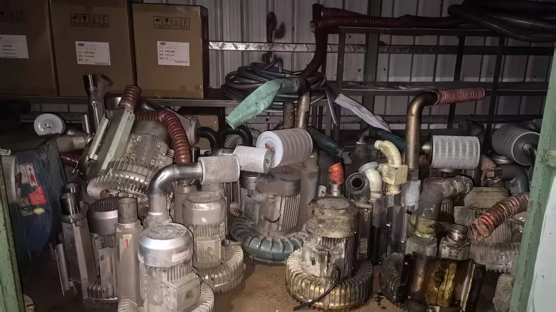
Those details matter because a 4.3 kW regenerative blower may have been selected for pressure that TW1500B cannot provide. A large energy opportunity does not override the airflow-pressure requirement, relief arrangement or process acceptance.
Quick Answer
The replacement is possible in a heavily oversized application, but the burden of proof is high. Confirm the old stage arrangement, pressure or vacuum point, airflow, system resistance and protective devices. TW1500B must cover the combined duty and pass the real process; otherwise assess TW2000B or another suitable model.
First Identify What the Existing Blower Actually Is
“Regenerative blower,” “side-channel blower,” “ring blower” and “vortex blower” often describe overlapping equipment. The generic name does not tell a supplier whether the unit is single-stage, two-stage, arranged for pressure or used on its suction side.
Photograph the full nameplate and both connections. Record manufacturer, model, power, voltage, phase, frequency, rated current and any pressure or vacuum information. Obtain the original curve and manual where possible. Note any changed motor, removed relief valve, altered silencer or non-standard pipework.
A two-stage regenerative blower may cover a pressure range that a single lower-power proposal cannot. Treat stage count as an early screening item, not a detail to discover during installation.
Distinguish Pressure Duty from Vacuum Duty
For pressure service, record positive gauge pressure and airflow at defined locations. For vacuum service, record inlet vacuum, airflow and the location of the measurement. Do not compare a discharge-pressure endpoint with a suction reading simply because both use kPa.
Cooling and loading can differ between the two arrangements. State which connection is the process side, where air is filtered, where it exhausts and whether hot discharge air can recirculate. The replacement must be evaluated for the actual configuration.
In vacuum systems, leaks increase the air the blower must handle. In pressure systems, outlet restriction increases required pressure and changes flow. Diagnose the system before assigning every symptom to the old blower.
Define the Combined Operating Point
The 4.3 kW rating cannot tell how much air the process uses. Measure pressure or vacuum at a named point, airflow by a stated method and process output under normal and peak conditions.
Map the filter, silencer, pipe, bends, valves, branches and terminal devices. Identify relief valves, vacuum-break valves, check valves and drains. Record which outlets run simultaneously. A line drawing is especially valuable when the blower is remote from the process.
Maximum airflow and maximum pressure are separate performance-curve endpoints. The candidate must supply the required airflow at the required pressure or vacuum; comparing one old maximum with one new maximum does not establish equivalence.
Compare TW1500B and TW2000B for Screening
For TW1500B and TW2000B, request released curves for the applicable pressure or vacuum arrangement and the delivered electrical data. Compare both candidates at the measured required duty; motor class and separate catalogue endpoints cannot establish suitability.
Maximum airflow and pressure or vacuum values are separate curve points; confirm the applicable released variant before selection.
Confirm voltage, phase, command range and protection from the delivered model data. Use the applicable released pressure or vacuum curve; neither motor class alone proves suitability.
TW1500B should leave the review when the required point lies outside its verified envelope. TW2000B may be evaluated as another candidate, but must be checked at the same real duty and pressure or vacuum arrangement.
Audit the Protective Devices
Regenerative blower systems often rely on relief or vacuum-break protection to limit abnormal operation. Record device type, location and setpoint. Do not remove it merely because the new package has electronic control; confirm the required protection with the final system design and manual.
A closed valve or blocked line does not create useful pressure. It moves the blower to another load condition and may increase heat or trigger protection. Filter loading can do the same gradually. Include both clean and service-limit filter conditions in the operating review where relevant.
Wet processes need backflow protection. Condensate or process liquid entering the blower can cause damage. Towwind’s supplied specification warns against water immersion and condensate backflow, so the retrofit must include appropriate routing, drainage, check devices or separation for the application.
Evidence That the 4.3 kW Unit Is Oversized
Useful evidence includes a verified process pass at substantially reduced old-blower output, a normal operating point far inside the old curve, permanent throttling or bypass, and unused original branches. Running current below a nameplate value is only supporting context; it does not quantify available airflow and pressure.
Where safe and permitted, perform a controlled output-reduction test on the existing system. Record pressure or vacuum, airflow basis, process result, input power and operating configuration at each step. Do not create an unsafe restriction or exceed the old equipment’s permitted range.
If the process begins to fail before demand reaches a verified TW1500B point, stop pursuing the smaller model. The objective is a reliable retrofit, not proving a predetermined power reduction.
Check Electrical and Mechanical Integration
Confirm the exact 220 V or 380 V variant, phase, frequency, grounding, protection, command signal, feedback and alarm behavior. A 4.3 kW induction-motor starter cannot simply be assumed suitable for the new electronic package.
Verify mounting, inlet and outlet interfaces, adapters, flexible connection, pipe support, cooling clearance and filter access from the final drawing for the exact delivered unit.
The specification describes indoor use and requires a clear inlet. Review ambient heat, chemical mist, dust, water exposure and exhaust recirculation. In multi-blower systems, design isolation so one running unit cannot drive another.
Measure Energy at Equivalent Process Output
Use measured input power or accumulated kWh at the same electrical boundary for old and proposed configurations. Record the process mode, pressure or vacuum, airflow basis and acceptance with every energy result.
Saving percentage = (old energy − new energy) ÷ old energy × 100%
Do not use (4.3 − 1.5) ÷ 4.3 as the project result. Rated power is not measured consumption. Establish any saving from comparable old and new energy data at the required pressure or vacuum duty and accepted process output.
For annual cost, weight each production mode by real hours. Include controller, installation, adapters, wiring, commissioning and planned downtime when assessing payback.
Commission Both Performance and Protection
Test the most demanding normal condition with the complete air path. Record command, feedback, electrical input, pressure or vacuum, airflow method, filter and valve state, alarms and process result. Run long enough to reveal thermal behavior and stability.
Test relief or vacuum-break response, check-valve function, liquid protection and duty/standby changeover where applicable. Stop for repeated alarms, inadequate process output, unstable readings, unusual noise or excessive heat. Do not alter protection limits to force acceptance.
Retain the approved settings and readings as a maintenance baseline. If the system later changes branches, depth, line speed or pipework, repeat the operating-point review.
Final Decision
A 4.3 kW regenerative blower can be replaced by TW1500B only when measurement proves extreme oversizing, the exact pressure or vacuum duty sits inside verified performance, protective functions are preserved and the process trial passes with margin.
Where any of those conditions fail, review TW2000B or another properly sized solution. Send Towwind the old model and stage arrangement, operating point, air-path drawing, protection scheme, electrical details, load profile and acceptance criterion. That information supports a technically honest recommendation instead of a risky nameplate comparison.
Keep the original baseline and final commissioning record together so later maintenance changes can be separated from the approved retrofit condition and energy result.
Retain the verified duty data after commissioning.
Frequently Asked Questions
Can a 1.5 kW blower replace a 4.3 kW regenerative blower?
Only when the old unit is heavily oversized and TW1500B covers the verified airflow-pressure or airflow-vacuum point with process margin.
Why does the old stage count matter?
A multi-stage regenerative blower may have been selected for higher pressure. A smaller candidate cannot be approved until its verified curve covers that real requirement.
Can pressure data be used for a vacuum application?
Not without verified manufacturer data for the intended configuration. Record the actual vacuum duty, airflow and cooling arrangement and evaluate it directly.
Should the old relief valve be removed?
Do not remove or change protection without an engineered review. Confirm relief, vacuum-break and backflow requirements for the complete new system.
How should energy savings be verified?
Measure kW or kWh while old and new systems deliver equivalent accepted output at the same duty. Do not calculate savings from rated powers.