
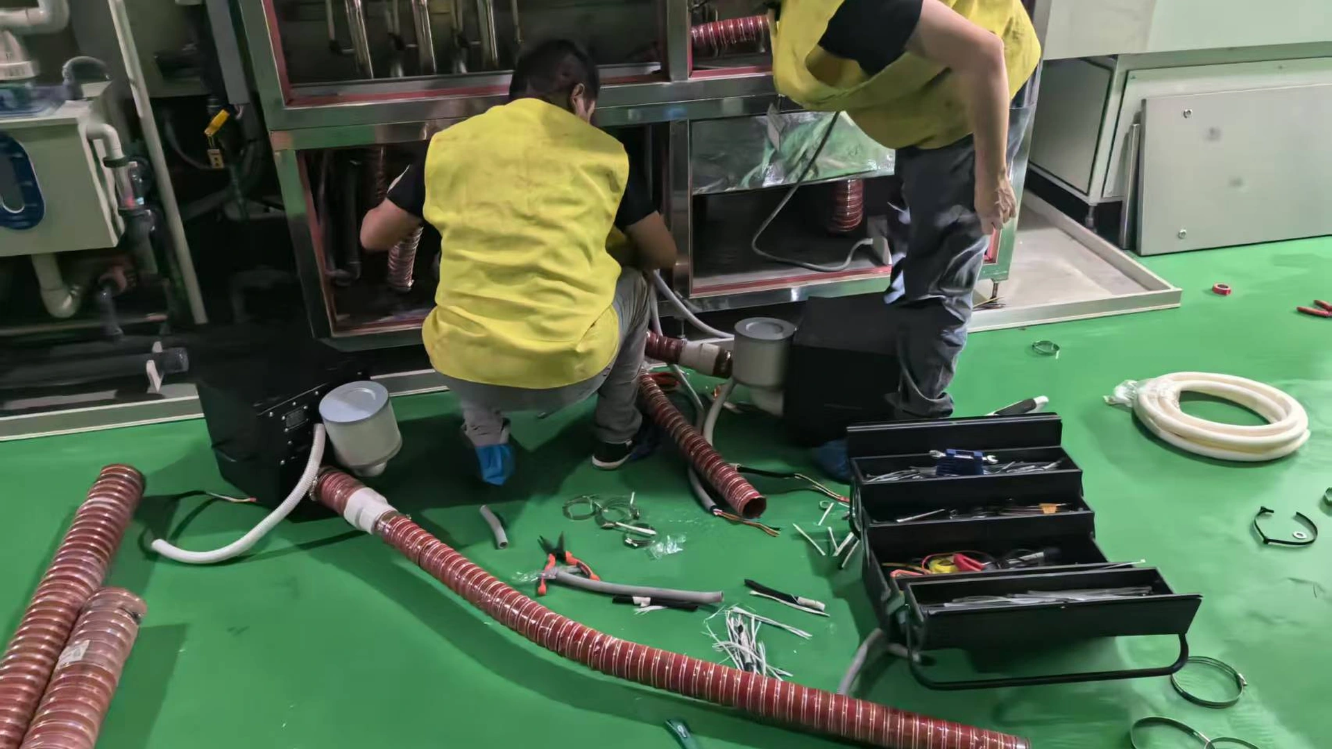
This is the lowest-risk comparison in the four power-replacement articles because the ratings are relatively close, but it still needs field evidence. Record the old operating point, normal and peak modes, electrical input and process acceptance before approving the change.
Quick Answer: Can a 1.5 kW blower replace a 2.2 kW ring blower?
A proposed TW1500B may be evaluated against a 2.2 kW ring blower where the existing unit appears oversized or throttled. Do not treat the motor-rating gap as replacement proof; require the released curve at the measured duty, delivered electrical compatibility and a representative process test.
Test the Replacement Claim Before Ordering
A smaller rating is acceptable only when the proposed blower covers the old system duty and passes the process test. Treat the 2.2 kW nameplate as identification, not as the selection point. Obtain the old model, curve if available, running current, pressure, airflow basis and normal valve positions.
Inspect the system before measuring. A dirty filter or partly closed valve may make the recorded point unrepresentative, while a large bypass may reveal that the original blower has excess capacity. Record both the physical condition and the operator’s normal settings.
Screen the TW1500B Against the Duty
TW1500B identifies a 1.5 kW model family, not a verified replacement duty. Obtain the released curve and confirmed electrical data for the exact variant, then compare available airflow at the site’s required pressure and conditions.
Confirm current, supply, frequency, protection and control interface from the delivered nameplate and manual. Do not use an unreconciled source-sheet current or assume every controller command is an acceptable operating point.
Measure the old system pressure at a named point and airflow by a stated method. If only nozzle velocity is available, keep it in m/s with its location and area; do not present it as total m³/h without sufficient data. Test normal and demanding branch configurations.
Do not rely on the original purchase specification alone. Pipework may have been changed, outlets may be isolated and operators may have adjusted valves since commissioning. Record what is installed today. A simple marked sketch should show the inlet filter, silencers, pipe diameter and length, bends, valves, branches and terminal devices.
Pressure at the blower outlet is not automatically the pressure at the process. When the existing gauge is remote or poorly located, state that limitation. If airflow is calculated, preserve the calculation and assumptions. Mark each value as measured, calculated, catalogue data or unknown.
| Check | Continue when… | Stop or investigate when… |
|---|---|---|
| Pressure | Verified duty has curve margin | Released curve lacks the required pressure margin |
| Airflow | Curve covers flow at required pressure | Only a separate maximum-flow endpoint is cited |
| Process | Acceptance is measurable | “Feels similar” is the criterion |
| Supply | Voltage, phase and controls match | Wiring or protection is unresolved |
Why the 1.5 kW Option May Work
The opportunity is strongest when the old blower is oversized, excess air is throttled or bypassed, or demand changes during production. Electronic adjustment can match approved modes without discarding as much excess air.
A maintenance history can support this assessment. Persistent high housing temperature, frequent filter loading or repeated operation against a relief path may indicate that the system and blower are poorly matched, although none of those observations proves that TW1500B will fit. Conversely, a 2.2 kW blower running reliably near the edge of its curve may leave little room for a smaller proposal.
A controller’s command range does not make every setting suitable. Low output must pass the process test, while peak demand must remain inside the verified performance envelope and documented cooling limits.
Check Every Retrofit Interface
Verify mounting, connections, adapters, flexible coupling, pipe support, cooling clearance and filter access from the final drawing. The specification describes indoor use and warns against water immersion, blocked inlets and condensate backflow.
Confirm package dimensions, weight and connections from the final drawing for the exact delivered variant. Do not force misaligned rigid pipe onto the casing; independently support the air line and use a suitable flexible connection where required.
Confirm voltage, phase, frequency, grounding, protection, start/stop command, feedback and alarms. For duty/standby arrangements, provide isolation so one unit cannot push air through the other and include changeover in the test.
The installation plan should also state who supplies the controller wiring, adapters, filter, isolation components and PLC changes. Without that scope, two quotations that appear to offer the same blower may carry very different installed costs and downtime exposure.
Compare Energy with a Meter
Use the same electrical boundary for both configurations. Accumulated kWh over representative production is useful when load changes. Log blower setting, pressure, airflow basis and process acceptance with every reading.
Saving percentage = (old kWh − new kWh) ÷ old kWh × 100%
Do not calculate savings as (2.2 − 1.5) ÷ 2.2; those are rated powers, not measured consumption. Compare old and proposed real input only when both systems meet the same accepted duty and use representative operating hours.
Build the annual estimate from the verified load profile. Separate full production, reduced production and idle running if their inputs differ. Multiply the measured reduction in each mode by its annual hours, then apply the site tariff. Include installation and commissioning costs before quoting a payback period.
Run a Controlled Trial
Operate the complete air path at normal and peak duty. Record old and new pressure at the same location, airflow or velocity by the same method, production rate, accepted result, electrical input, filter and valve condition, commands and alarms.
Run long enough to reveal heat or changing resistance. Preserve the accepted settings as a maintenance baseline. If the process passes but energy does not match the proposal, check the measurement boundary and operating mode before drawing a conclusion.
Stop the trial and investigate abnormal current, repeated alarms, unstable pressure, inadequate drying or aeration, unusual sound or excessive temperature. Do not increase protection limits or continue raising the command simply to force acceptance. A failed trial is useful evidence: it may identify a hidden restriction, an incorrect duty assumption or the need for another model.
After a successful trial, document the approved command for each production mode, instrument locations, readings and responsible sign-off. Train operators not to treat the highest setting as the normal setting unless the process requires it.
Make the 2.2-to-1.5 kW Decision
Approve the replacement when TW1500B covers every required mode, integrates safely, passes acceptance and supports the cost case. Reject or revise it when pressure margin is inadequate, required airflow is outside verified data, or interfaces remain unresolved.
Purchasing should make approval conditional on the stated duty and scope. If the factory later adds nozzles, increases line speed or changes pipework, the accepted operating point may no longer apply. Recheck the system rather than assuming the original replacement decision automatically covers the modification.
Send Towwind the old nameplate, measured operating point, air-path layout, electrical supply, annual hours and acceptance criterion. This evidence answers the replacement question without treating motor ratings as air-performance data.
Keep both the pre-retrofit record and the final accepted record. Together they provide the evidence needed for later maintenance, energy verification and any future capacity change.
Keep the accepted readings with the equipment record.
Frequently Asked Questions
Can a 1.5 kW blower replace a 2.2 kW ring blower?
Yes, when TW1500B covers the old system’s real airflow-pressure duty and passes the process test. The difference between 1.5 and 2.2 kW ratings is not proof by itself.
What is the quickest reason to reject TW1500B?
Reject or investigate further if the required pressure or airflow lies outside the released TW1500B curve with appropriate margin, or if verified duty data is unavailable.
Can the separate maximum-flow and pressure endpoints be combined?
Do not assume so. Maximum airflow and maximum pressure are separate endpoints. Use the applicable curve or verified combined-duty data.
Which electrical version should replace the old blower?
Match the delivered model’s voltage and phase to the site supply and machine design; verify protection, wiring and control requirements from the final manual.
How should savings be calculated?
Compare measured kW or kWh while both blowers deliver equivalent accepted output. Do not subtract their nameplate ratings.
What should the acceptance trial include?
Test normal and peak modes and retain pressure, airflow basis, energy, settings, filter and valve condition, process result, alarms and approval.