
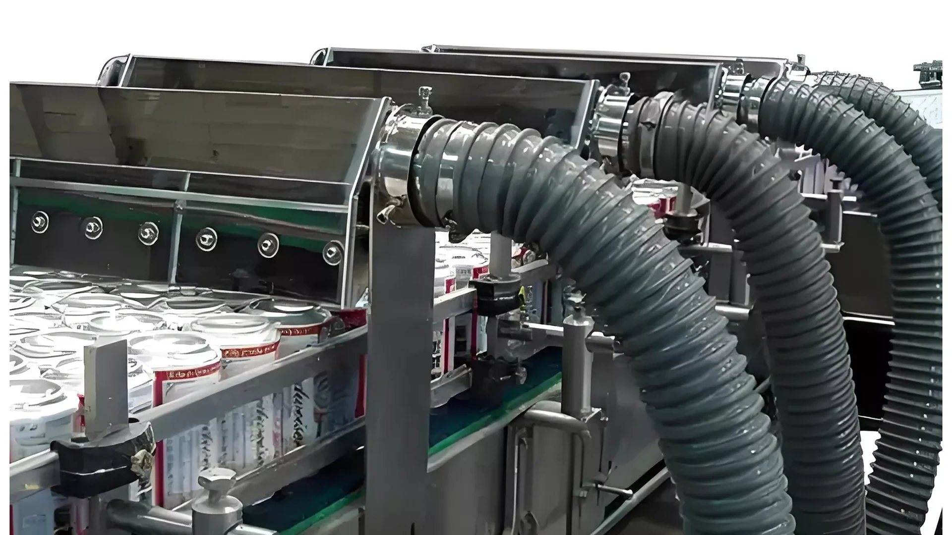
An industrial air-knife system is easier to review when the drawing shows how air must travel from the blower to the process. A photograph may explain the general machine, but it rarely provides the dimensions, operating modes or branch details needed to evaluate pressure loss, access and interfaces.
This checklist helps equipment builders and plant engineers prepare a layout drawing for discussion with a blower or air-knife supplier. It is a documentation guide, not a shortcut for airflow calculation or a model recommendation.
Start with the product path and process objective
Show the product travel direction, working width, conveyor height and the point at which cleaning, drying, cooling or blow-off must occur. Identify the surface or feature that needs useful air and the downstream condition used to judge success.
Record the normal product range rather than drawing only one nominal size. If containers, panels or components change format, show the minimum and maximum envelope and any guide rails that may shield the air.
Add the normal line speed and any slower or faster operating modes. A layout drawing should make clear which knives operate together in each mode.
Dimension every air knife
Give each air knife a unique tag, such as AK-01 or AK-02. For every tag, show:
- effective outlet length;
- slot or hole arrangement and specified opening;
- angle relative to the product path;
- stand-off distance to the target surface;
- useful coverage width;
- inlet size and orientation;
- adjustment range, if the design allows adjustment.
Do not replace these details with a single note such as “standard air knife.” Different lengths, openings and positions can create different airflow demands and pressure losses.
Show branches, manifolds and pipe dimensions
Trace the air path from the blower outlet to each knife. Mark pipe or hose internal diameter, approximate straight length, major bends, reducers, flexible sections, manifolds, valves and branch take-offs. Identify which elements are already fixed and which may be changed.
Where branches are unequal, include enough dimensions to compare the shortest and longest paths. A symmetrical sketch should not be used when the installed branches are materially different.
If balance valves or orifices are planned, show their location and intended function. Their pressure loss must be considered at the required flow; they are not a substitute for an adequately sized supply path.
Identify the blower and air-treatment location
Show the proposed blower position, inlet direction, outlet direction and mounting level. Add the inlet filter, silencer, flexible connector or other air-treatment components that are part of the actual system.
Include the available service and cooling clearance. A blower that fits the drawing footprint may still be difficult to maintain if the filter, electrical cover or connection cannot be reached.
If the environment contains water, dust, chemicals or elevated temperature, note the condition rather than assuming the supplier will infer it from the application name.
Add electrical and control interfaces
The layout or its referenced interface sheet should identify the available voltage, phase and frequency, control command, start/stop logic, alarm connection and any interlock with the production machine.
Show where the local isolator, control cabinet and cable entry are expected. Do not use a drawing to imply that an electrical configuration has been approved when the site supply is still unverified.
Mark measurement and acceptance points
Provide safe, accessible locations for pressure measurement and any airflow or velocity checks required by the project. Label whether a pressure point is at the blower outlet, manifold, branch or air-knife inlet; values from different locations are not interchangeable.
Add the product inspection point used for acceptance. For a drying process, this may be the air-knife exit and a downstream quality station. For cleaning or blow-off, define the observable condition without inventing a universal pass limit.
The drawing should also show drains, guards or enclosure features that can influence the air and water path.
Separate simultaneous and alternative operating modes
If all knives operate together, say so. If valves select different product formats, provide a simple operating-mode table that lists the active knives for each mode. The supplier needs the simultaneous demand and the governing branch condition, not the sum of every device that is never active at the same time.
Keep future expansion separate from the current design case. An unlabelled spare branch can cause confusion about the duty that must be reviewed now.
Include known constraints and unknowns
Mark dimensions that are confirmed, estimated or still to be measured. State restrictions such as maximum machine width, fixed pipe penetrations, hygiene zones, noise limits supplied by the project, or shutdown windows for installation.
Unknown information is acceptable when it is visible. A drawing that clearly marks an open item is more useful than a precise-looking dimension that has not been verified.
Use a drawing register for technical review
Give the drawing a number, revision and date. Keep a short change record when knife position, pipe diameter or operating mode changes. Supplier comments should refer to the same revision used for quotation and commissioning.
Before requesting a model review, send:
- the current layout drawing and operating-mode table;
- product range and line-speed information;
- knife or nozzle data sheets;
- pipe, hose, filter and valve details;
- site electrical and environmental information;
- existing measurements, with locations and methods;
- the project-defined acceptance condition.
Towwind can then review the stated operating conditions and identify missing information. The final blower selection must still be checked against model-specific performance data and the actual system resistance.
Frequently Asked Questions
Is a machine photograph enough for an air-knife blower quotation?
Usually not. A photograph helps explain the application but does not reliably show nozzle openings, pipe dimensions, branch lengths, simultaneous modes or the measurement locations needed for a technical review.
Must every bend and fitting be shown?
Show the components that materially affect the air path and provide enough geometry to estimate or verify system resistance. Minor fabrication detail can remain on a separate drawing.
Should future air knives be included in the current duty?
Only when the project requires them to operate with the current system. Label future or spare connections separately so they are not confused with the present simultaneous operating mode.
Does a complete layout drawing confirm the blower model?
No. It supplies the geometry and interface evidence needed for review. Required airflow, pressure, system losses and model-specific performance still need to be evaluated together.