
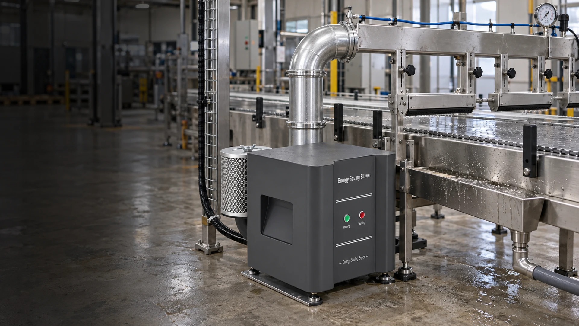
A blower may start cleanly while the first products leave a drying line wet. The cause may be a nozzle aimed at the wrong side, a guide rail that shifts containers away from the air stream, or water blown onto the next product. None of those problems appears on the blower’s nameplate.
Drying line installation checks should cover the whole path from wet product to downstream acceptance, not just the air-supply unit. Before the first loaded run, confirm that the product travels through the intended drying zone, air reaches the difficult surfaces, displaced water has somewhere to go, and the blower system is connected and controlled as designed. The first product trial then tests those assumptions at realistic speed and incoming wetness.
This guide is for blower-fed air-knife or similar industrial drying equipment. It does not prescribe a universal nozzle angle, gap or blower setting; those depend on the product, geometry, line speed and selected hardware. Electrical and mechanical work must follow the final manuals and site safety procedures.
Start with the acceptance point downstream
“Looks dry at the air knife” is usually too vague. A PCB may need a defined region dry before inspection or the next process. A bottle may need a dry label panel and cap area. A washed component may need no visible droplets in a recess before packing. The line owner should identify which surface matters and where it will be inspected.
Write down the product variants, normal and maximum production speed, incoming water condition and the next operation. A line may dry one item successfully yet struggle when product spacing narrows or a wider format arrives. Do not let the first empty-belt test become the only acceptance evidence.
The buyer should also ask what happens to a failed item. Will it be rejected, recirculated or allowed downstream? A drying line is part of a process; its acceptance criteria should match the quality consequence of residual water, not a generic claim of “high-velocity air.”
Check the product path before adjusting the air
Confirm that guides, belts, fixtures and transfer points position products consistently through the drying zone. If a guide rail leans a container or a board carrier moves side to side, the effective nozzle gap changes during production. Adjusting blower speed may hide that mechanical issue on one product size while wasting energy on every other size.
With the machine safely isolated as required, review clearances along the conveyor. Look for a nozzle or hose that could touch a tall product, a guard that intrudes into the air stream, or a changeover part left in the wrong position. Verify that the product cannot rotate or tip in a way the drying design did not allow for.
Pay attention to product spacing. A line that tests one item at a time may see a different airflow pattern and water carryover when items run close together. That is a reason to plan a loaded trial at the intended throughput, not to assume that a single sample proves the installation.
Inspect nozzle coverage and mounting
Each air knife or nozzle should aim at a specified surface. Check its mounting rigidity, orientation, slot or outlet condition and adjustability against the approved layout. A small movement in a bracket can send water toward a protected recess or back onto the next item. If there are several knives, check the sequence in which they contact the product, not only their individual positions.
Do not copy a nozzle angle from another application. A flat panel, a round bottle and a complex machined component present different surfaces. The right position depends on how the air displaces water and where the water can leave. The practical test is whether the entire critical surface remains acceptable across the actual product path and speed range.
Inspect for blocked slots, damaged lips and uneven distribution along a long knife. Record nozzle settings before the first run so a later change has a reference. If the drying arrangement has adjustable brackets, mark the approved position after successful acceptance. Otherwise routine cleaning or a product changeover may quietly return the line to an untested setting.
Confirm that removed water can leave the machine
Air knives move water; they do not make every droplet disappear. Displaced liquid may collect on a guard, drip from a cover, splash from a belt or rewet the product after it leaves the main air stream. On some lines, this is the real reason a downstream label or inspection step fails.
Check trays, drains, splash guards and the direction of blow-off. Look at low points in the enclosure and at the transition into the next station. A drain that is present but inaccessible or blocked during the first trial will not help production. If the process includes wash water, chemicals or other liquids, disposal and materials need review under the site’s process requirements.
Keep process cleanliness separate from the word “oil-free.” A blower that does not add oil to its air supply does not by itself make a drying system suitable for food-contact or other controlled hygiene duties. Inlet location, filtration, piping materials, cleaning method and site requirements still matter.
Walk the air path from inlet to the last nozzle
The selected blower must serve the installed air path, not the simplified layout used for a preliminary quotation. Check the inlet condition, filter, silencers, hoses, manifolds, branch valves and all outlet connections. Look for loose joints, crushed hose, unsupported pipework and reducers or sharp bends added late in assembly.
Confirm the final filter and valve positions. If a filter is difficult to reach, it may be neglected; if a valve can be left partly closed during production, the pressure available at the nozzles can differ from the blower outlet reading. For a multi-knife arrangement, check that each branch intended to operate simultaneously is open and connected correctly.
Place measurement points where they answer the acceptance question. A blower discharge reading can help diagnose the unit, while a manifold reading may better represent supply near the knives. Neither alone proves the product is dry. Label the measurement locations on the drawing and use the same locations during later troubleshooting.
Verify blower installation and electrical readiness
The drying application does not excuse basic blower installation checks. Confirm that the exact delivered unit and controller match the approved specification and final manuals. Review mounting, pipe support, cooling access and the expected operating schedule. A flexible connection should not be used to pull an unsupported pipe into place.
Qualified electrical personnel should verify the site supply, protective arrangement, grounding and control connections before energization. If the machine uses a PLC start command, speed reference, run feedback or fault signal, test those interfaces under the approved procedure. A local blower start does not prove the conveyor will wait for air or stop feeding product when a required air condition is lost.
The machine sequence should be explicit. Does the blower reach its intended state before wet product enters? What happens if the blower faults while products are between the washer and the drying station? Does the line reject or stop on a low-air condition, if the design includes such detection? Those answers should come from the machine design and risk review, not be invented during the first shift.
Plan the first loaded test as a controlled comparison
Run with the normal guards, filters, hoses and product guides installed. Start at an approved mode and move to the demanding normal condition only after the system is behaving as expected. The test should include the product format, incoming wetness and line speed that matter to the buyer. If the factory can test only with a surrogate product, record that limitation and keep site acceptance open.
Log the blower model and setting, pressure at named points, electrical input boundary where measured, nozzle position, product spacing, process result and any alarm or abnormal observation. Check the first item, a sustained sequence and the downstream condition after the drying zone. A few wet pieces appearing only after the enclosure fills with spray are different evidence from a uniformly wet first piece.
When a defect appears, change one factor at a time where practical. Re-aiming a knife, opening a valve and increasing blower speed together makes it hard to know which correction mattered. If a setting change solves the result, record both the earlier and approved settings. The goal is a repeatable operating condition, not a one-off demonstration.
| Pre-start review | What the buyer should be able to verify |
|---|---|
| Product path | Guides and spacing hold every tested format in the intended drying zone |
| Air delivery | Nozzles, branches, filter and pipework match the approved layout |
| Water exit | Displaced liquid does not collect or rewet downstream product |
| Controls | Blower readiness, faults and machine response work as designed |
| Test plan | Speed, wetness, product format and acceptance location are defined |
Where Towwind fits into a drying-line project
A Towwind Energy Saving Blower may be considered for a suitable drying line or as a replacement for a traditional ring or side-channel blower. The selection still depends on the combined airflow and pressure required by the final nozzle layout, the system resistance, the run schedule and the electrical and control arrangement. A blower with a lower motor rating is not automatically the better drying solution.
For a Towwind recommendation, send the nozzle count and geometry, branch layout, pipe and filter details, product formats, line speed, incoming wetness and acceptance criterion. Ask for the proposed operating point and what will be verified during the loaded trial. If a wet area remains, first determine whether the issue is nozzle coverage, water management, air-path loss or inadequate supply at the required point before simply increasing speed.
Energy savings should be compared only while the old and proposed arrangements achieve the same accepted drying result. Measure electrical input at a consistent boundary and account for actual operating hours by mode. No percentage can be promised from the product name or the difference between motor nameplates.
A useful release decision
The line is ready for its first product run when the product path and air path match the design, water can leave without rewetting, the blower and controls have passed their separate pre-start checks, and the loaded-test criteria are written down. It is ready for acceptance only after the real product meets the downstream requirement at the agreed operating conditions.
That distinction helps purchasing and production avoid an expensive misunderstanding. A machine can be safe to test without yet being proven ready for continuous production. Keep the open conditions visible and close them with a recorded trial rather than a verbal “it looks dry.”
Frequently Asked Questions
What should be checked before starting an air-knife drying line?
Confirm the product path, nozzle aim and coverage, filter and pipework condition, water drainage, blower installation, electrical supply and machine controls. Define the product format, line speed and downstream dry-surface criterion for the first loaded test.
Does a running blower prove the drying line is ready?
No. The product may miss the intended air stream, experience inadequate pressure at the final nozzle or be rewetted downstream. Test the assembled line with representative wet product at the agreed speed and inspect the required surface.
Should blower speed be increased when a dry area is missed?
Not automatically. First check nozzle position, product alignment, blocked or closed branches, filter condition and water carryover. Additional blower output may be needed, but the problem should be identified before increasing power.
Where should pressure be measured on a drying line?
Use locations that support the decision being made. Blower discharge pressure can help assess the unit; a manifold or branch point may better indicate supply near the air knives. Record the exact location and do not treat pressure as a substitute for a product-drying test.
Can an energy-saving blower guarantee a dry result with lower electricity use?
No. Suitability and energy use depend on nozzle demand, pipe losses, operating point, speed and the accepted drying requirement. Compare complete systems at equivalent process output using measured electrical input.