
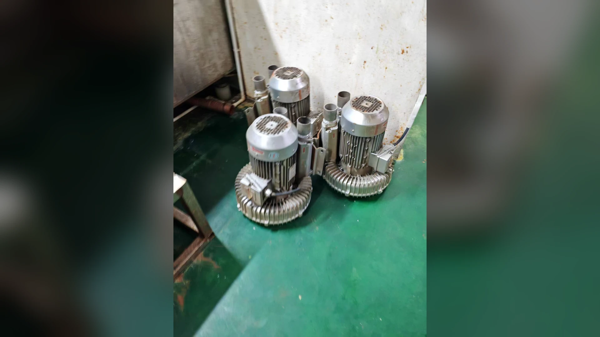
An aquaculture aeration system needs a plan for the period after a blower or power source fails. A spare machine in a storeroom does not deliver air during an outage. The useful design question is which ponds must continue receiving air, at what duty, and how quickly the backup path can be put into service.
The normal-duty selection is covered in Towwind’s aquaculture aeration guide. This article focuses on continuity when the normal air path is unavailable.
Define the failure cases
Separate at least three events: one blower stops while mains power remains available; the electrical supply to a group of blowers fails; and an air header or branch becomes unavailable. Each event has a different response. A standby blower on the same failed electrical circuit does not solve a site power loss. Two blowers connected to one blocked header are not independent at the point of use.
List the ponds or zones that need immediate support and the process measurements used to trigger action. The response plan should name who receives the alarm, how the fault is confirmed and which equipment can be started. Actual biological limits and response times must come from the farm’s operating plan, not a generic blower article.
Check backup capacity at the operating point
The backup source must deliver usable air at the pressure imposed by the water depth, diffusers and piping for the zones it will serve. Do not compare standby and duty units by motor kW alone. Define a minimum-service operating mode if full production capacity cannot be justified or supplied during a failure, and have the farm owner approve that mode.
If a common header allows one blower to serve several ponds, check valve positions and simultaneous branch demand. A plan that counts the sum of catalogue maximum flows without the shared-system pressure can substantially overstate available air. Towwind’s operating-point guide provides the air-side calculation approach.
Design a changeover that operators can execute
Document the normal valve lineup, standby valve lineup, start sequence, interlocks and the indication that air is actually reaching each critical branch. Label manual valves clearly. Where automatic changeover is used, test both the control signal and the final air-delivery result; a “run” contact does not prove that a pond receives air.
Keep the standby unit serviceable. A spare that has a blocked inlet, disconnected power or incompatible outlet fitting is not a backup. Include inspection and a scheduled start/test procedure in the maintenance plan. Record the last successful test and any corrective work.
Test the plan without creating an uncontrolled outage
Arrange a supervised changeover test under conditions the farm can safely tolerate. Record starting dissolved oxygen, normal and backup air pressures, actual branch operation, alarm delivery and the time to restore service. Test a representative failure of the duty blower and, where the site plan allows, the power-loss response. Restore the original configuration and verify normal readings before ending the test.
An emergency plan should be understandable to the person on shift, not only to the designer. Keep a current contact list, equipment identifiers and the safe switching steps near the control point.
What to send for a backup blower review
Provide pond count, water depth, diffuser types, normal and minimum-service airflow, branch pressures, electrical arrangement, control logic, ambient conditions and the intended failure scenarios. Towwind can check the TW750, TW1500 and TW2000 against the stated backup duty and installation requirements. Discuss the documented application before treating any series as a universal standby choice.