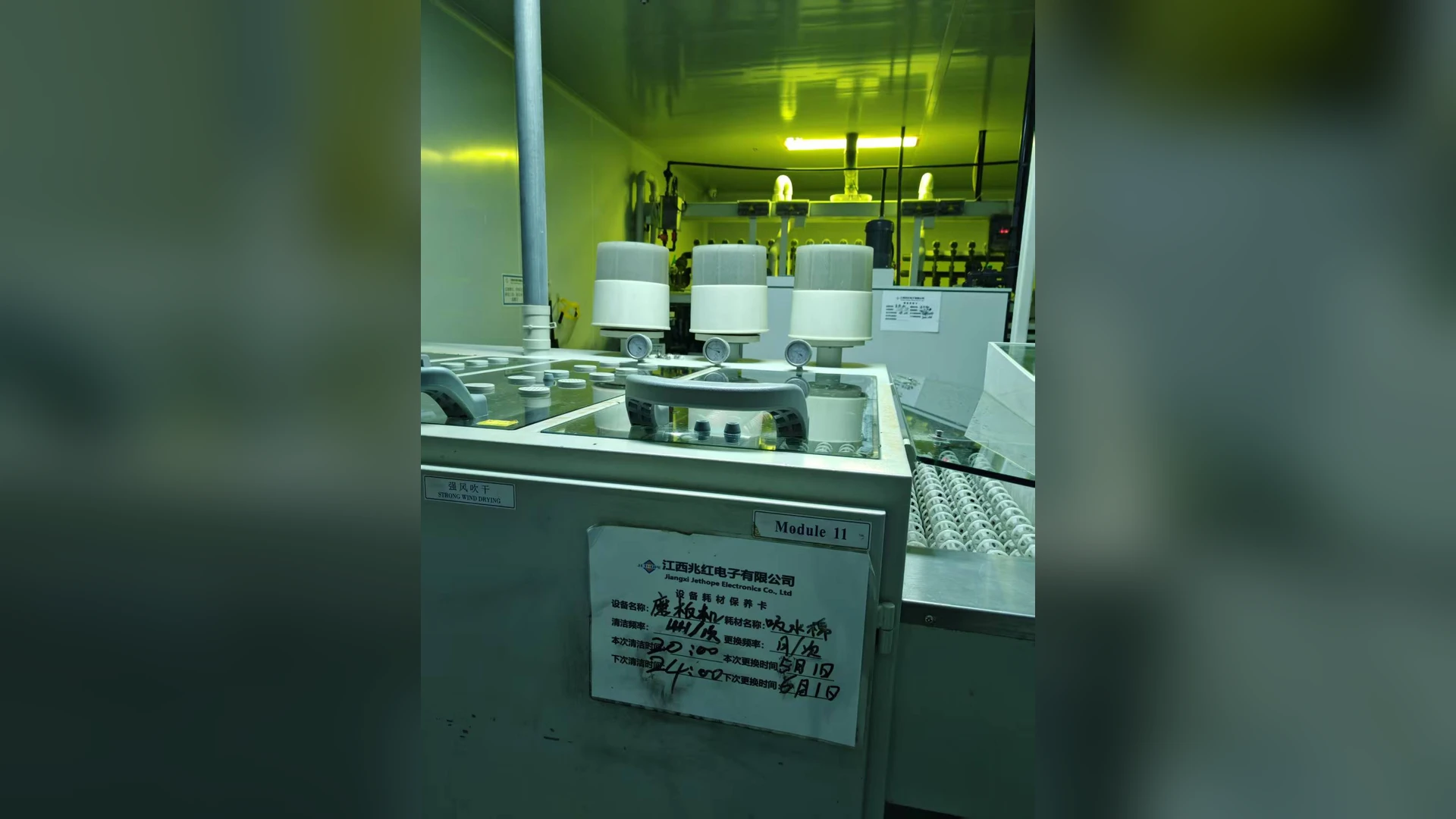
A board can look dry across its flat surfaces while liquid remains in plated through-holes, cutouts or fixtures. Turning up the blower may improve the visible surface and still leave the trapped water unchanged. The useful question is where the water enters, how it can leave, and which drying stage actually reaches that location.
This article focuses on a specific residual-water defect. For a complete airflow and pressure specification, see Towwind’s PCB blower sizing guide.
Confirm the defect before changing the air system
Inspect boards immediately after washing, after each drying stage and at the final inspection point. Mark the affected hole types and locations on a board drawing. Record whether the defect appears only on dense areas, near panel edges, under a carrier, or at a particular line speed. Compare the same board design in several orientations when the process permits it.
Do not assume every mark is water. Residue from the wash or rinse chemistry, surface staining and rewetting after the air knife can resemble a drying failure. Use the site’s approved inspection method and acceptance criteria. The required dryness depends on the next operation; an electrical test, coating process or packaging step may have different limits. An IPC technical resource on in-line aqueous cleaning discusses why retained moisture can matter to later PCB processes, but the acceptance method for your line still needs to be specified locally.
Follow the water path through the machine
First inspect the incoming water load. Excess rinse water, pooling in a carrier or droplets falling from an upstream hood can overwhelm a dryer that was adequate before. Check whether a lower board surface, fixture pocket or conveyor component carries water into the next zone. Drainage and splash control often change the result more directly than a larger blower.
Next review the direction of the air. A jet that sweeps water across a flat surface may bridge a small opening instead of clearing it. Top and bottom knives should be assessed as a sequence: where does the first stage move the liquid, and can the following stage eject it rather than push it back? Examine nozzle angle, stand-off distance, exposure time, the board’s travel direction and any obstruction. Change one variable at a time so the cause remains clear.
Finally, check whether removed water is being carried back as mist. Wet guards, rollers or an enclosure surface can redeposit droplets after the nominal drying point. A second inspection location can distinguish incomplete removal from later rewetting.
Run a controlled trial
Choose representative boards that show the defect, including the most difficult approved format. Hold wash chemistry, rinse condition, conveyor speed and blower settings constant for the baseline. Record the number and location of wet features using the site’s inspection method. Then alter one mechanical or air-delivery variable, such as knife angle or a drain path, and repeat the same observation. Only after the geometry is understood should blower speed or a different blower be tested.
During each trial, record branch pressure, relevant airflow or outlet measurements, blower command and real electrical input where available. A higher gauge pressure alone does not prove that more useful air reaches the holes. Stop an adjustment that lifts or shifts boards, creates a new defect, or violates equipment limits.
When to review blower capacity
Request a blower duty review if the air-path and drainage checks are sound yet the accepted process still needs more air at the verified pressure. Document the number of active knives, their slot geometry, pipe and filter condition, simultaneous demand and the accepted production speed. Towwind can then compare the required operating point with the TW750, TW1500 and TW2000 curves as appropriate. Send the measured application data rather than selecting from motor kW alone.
The best outcome is a repeatable dry-board result at the required throughput. The size of the blower is only one part of that result.