
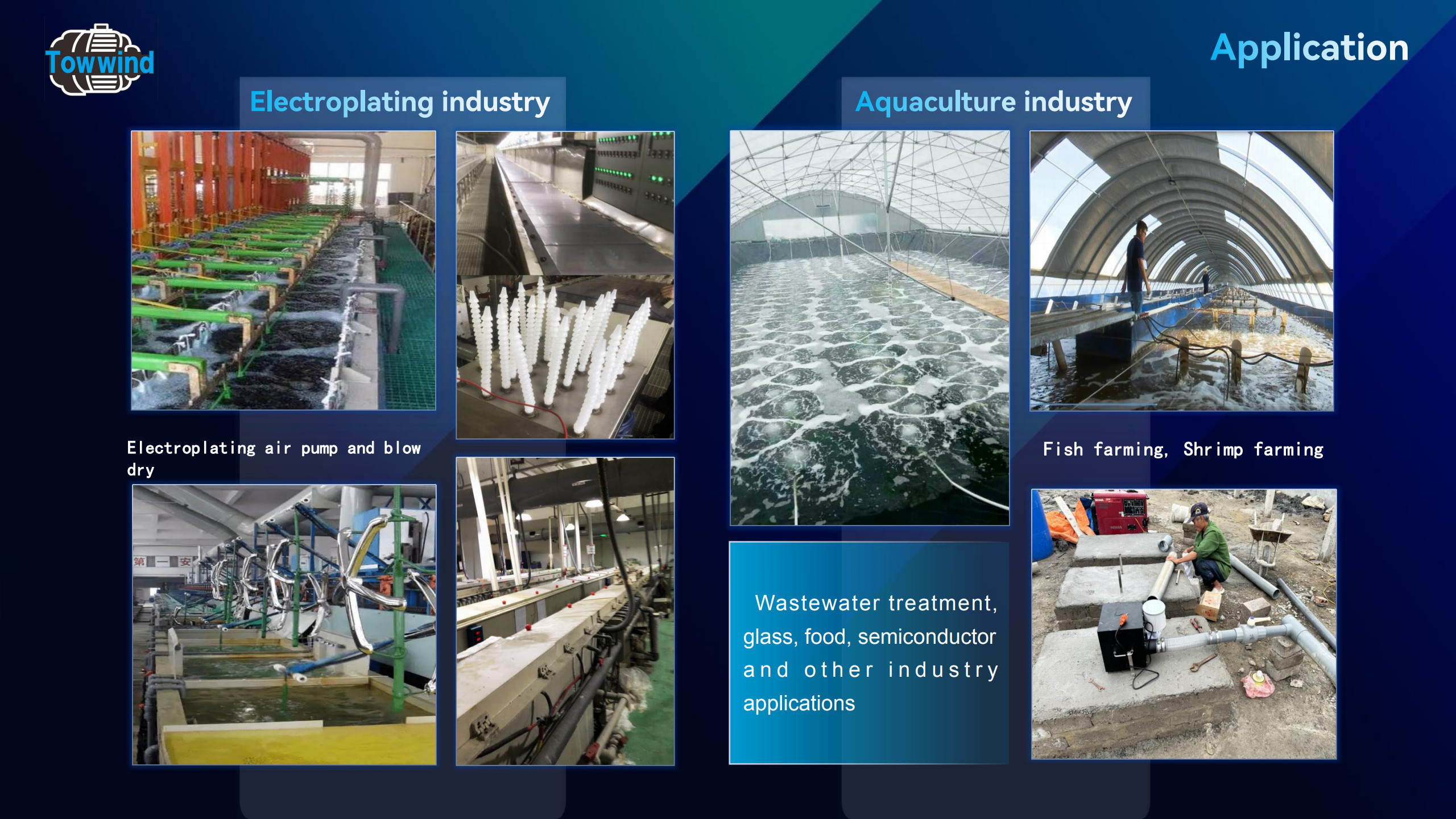
A replacement blower cannot be evaluated from the old motor rating alone. At a wastewater plant, the same machine may run against different basin depths, diffuser conditions and valve positions. A useful pre-survey records what the installed system actually does, where each reading was taken and what remains unknown.
This checklist is for plant engineers and operators preparing information for a wastewater aeration blower replacement review. It is a data-collection guide, not a method for choosing a model. The process engineer must confirm the treatment duty, and the supplier must check the resulting flow–pressure points against the exact equipment data.
Record the Existing Blower and Its Service
Photograph or transcribe the blower and motor nameplates. Record manufacturer, model, serial number, motor rating, supply voltage and frequency, and any controller or drive identification. Keep the equipment manual or performance curve if available. A nameplate identifies what is installed; it does not establish the air delivered at the basin.
List each blower’s normal role, typical runtime and operating hours by relevant mode. Note whether machines alternate, run together or serve different basins. If one unit is standby, record how it starts and which load it is expected to cover after a fault. Do not describe standby capacity as verified unless it has been tested against the operating network.
Describe the Treatment Duty When Each Reading Was Taken
Identify the treatment process, basins or zones served and the combination operating during the survey. Record influent or process-load information where available, together with dissolved-oxygen trends and other indicators used by the process team. Include normal, demanding and reduced-load conditions when they occur; one peak snapshot cannot describe the full service.
Record water depth for active diffuser groups, diffuser type and quantity, layout, service condition and planned diffuser changes. Airflow at the blower is not the same as oxygen transferred into wastewater. If a basin is missing its process target, mark that separately rather than treating present blower output as the required replacement duty. The process engineer or diffuser supplier should define any missing oxygen-transfer or minimum-mixing requirement.
Sketch the Air Path and Record Pressure Locations
Sketch the path from blower inlet through filter, discharge connection, common header, valves and branches to the diffuser groups. Add pipe sizes, approximate runs, fittings and available measurement points. Identify the deepest or otherwise most restrictive active path; the nearest basin is not automatically the controlling one.
Capture the operating state beside each pressure reading
Record discharge and selected downstream or branch pressures where safe, suitable instruments and taps are available. For each reading, note the exact location, units, instrument, water level, active basins, valve settings, blower command and time. Discharge pressure alone does not prove what reaches a remote diffuser. Rising header pressure may reflect fouling, a valve restriction or another changing loss; it does not by itself prove blower inefficiency.
State what is known about airflow
Record measured blower or branch airflow where reliable instruments exist, including location, units and whether the figure is actual or referenced to stated conditions. If airflow is calculated or taken from historical records, label the method and assumptions. If no defensible value exists, write “not measured” and identify who must establish it. Do not substitute catalogue maximum free-air flow for installed delivery.
Capture Power, Controls, Alarms and Failure Response
Record electrical supply, measured package input power where available, controller setting, command and feedback signals, operating schedule and automatic staging. State the measurement boundary: a motor-only reading and a complete blower/controller-package reading are not interchangeable. Note relevant alarms, shutdown history and the action taken when a sensor or blower fails.
Describe which blower runs, which can take over, how valves and check devices are arranged, and whether transfer has been tested. Include site constraints such as ventilation, inlet-air condition, maintenance access and electrical connection, but do not infer suitability for a new blower from these notes alone.
Compile a Supplier-Ready Site-Data Sheet
Give each important datum a status: measured, calculated, documented or unknown. A usable handoff includes both the value and its limitations:
| Field | Record with the value | If unavailable |
|---|---|---|
| Existing equipment | Nameplate, controller and any available curve | Identify missing documents |
| Operating mode and hours | Active basins, blower combination, time and duration | Request logs or a defined survey period |
| Process-air requirement | Process engineer’s basis, load/DO context and units | Mark as an engineering input still required |
| Airflow evidence | Measurement or calculation method, point and reference conditions | State “not measured” and assign verification |
| Pressure evidence | Instrument, discharge/branch location, valve state and water level | Identify a safe test point or calculation |
| Diffuser and pipe network | Depth, type, quantity, condition, pipe dimensions and sketch | Request drawings or field survey |
| Power and controls | Supply, input-power boundary, command, feedback and alarms | List missing electrical/control records |
| Reliability | Duty/standby sequence, tested transfer and failure response | Flag an untested contingency |
For each line, add date/time, source, units, measurement point and confidence or open question. Keep normal, reduced and demanding modes in separate rows. If diffusers or controls will change, mark the old and planned arrangements separately.
Hand Off Unknowns Before Requesting a Proposal
Review the sheet with process, maintenance and controls teams. Missing diffuser-loss information, uncertain minimum air service, unmeasured branch flow or untested standby transfer should be called out. Some gaps require a safe site test or calculation by the responsible engineer before a supplier can propose a defensible replacement.
The supplier’s next task is to verify airflow at corresponding pressure for each relevant mode on the exact proposed model curve. How to Define the Required Blower Operating Point explains that later step. If an energy comparison follows, use measured input at equivalent useful duty; How to Calculate Blower Energy Use Without Overstating Savings covers the calculation boundary. These links existed in this content package; their live status has not been verified here.
For a Towwind technical review, send the completed site-data sheet, network sketch, readings and list of unknowns. Towwind can then assess whether an Energy Saving Blower is worth checking against the plant’s actual duty. No model, saving or treatment result should be promised from a nameplate or incomplete survey.
Compare Towwind blower series
Use the requirements discussed above to compare the published specifications for TW750 750 W blower, TW1500 1.5 kW blower, and TW2000 2.0 kW blower. These links support comparison, not a model recommendation. Confirm airflow, pressure, voltage, duty cycle, operating point and installation conditions before selecting a series.
Frequently Asked Questions
Is the old motor rating enough for a replacement request?
No. Include the nameplate, but also record installed pressure, credible airflow evidence, basin conditions, operating hours and control/standby requirements.
What if the plant has no airflow meter?
Mark airflow as not measured. Preserve operating-state and process records, then ask the responsible engineer and supplier which calculation or safe site measurement is needed.
Why record valve state and diffuser condition with pressure?
They affect system resistance. Readings taken with different branches, water levels or diffuser conditions cannot be compared as though the network were unchanged.
Should standby performance be in the survey?
Yes. Record the intended failure response and whether changeover has been tested under the required service. Replacing one unit must not silently remove the plant’s reliability arrangement.